Ignition Wiring Harness Diagram – The first step is to look at the different terminals that are used in the ignition switch. These terminals serve for the Ignition button, Coil and Accessory. Once we know what these types of terminals are, we will proceed to identify the different parts of the Ignition Wiring Harness Diagram. We will also discuss the function of the Ignition switch and Coil. Then we’ll discuss the Accessory Terminals.
Terminals for ignition switch
An ignition switch has three separate switches that feed the battery’s power to various destinations. The ON/OFF position of the switch that controls the ignition is managed by the first switch, which provides power to the choke whenever it’s pushed. Different manufacturers use different color-coding systems that correspond to the conductors. OMC employs this system. A connector can be added to the ignition switch to add the digital Tachometer.
Although the majority of ignition switch terminals may not be original, the numbering for each one may not be in line with the diagram. It is important to first verify the continuity of the wires to determine if they’re plugged into the ignition switch correctly. This can be accomplished with a multimeter that is inexpensive. After you’re happy with the continuity of your wires, you’ll be able install the new connector. If your vehicle is equipped with an installed ignition switch the wiring diagram will differ.
In order to connect the ACC outputs to the auxiliary outputs of your car, you’ll need to first understand the way these two connections function. The ACC/IGN terminals act as the default connections on the ignition switch. The START/IGN terminals connect to the stereo or radio. The ignition switch switches the engine of your car ON and OFF. The terminals on older cars’ ignition switches are labeled by “ACC” as well as ST (for the individual magneto wires).
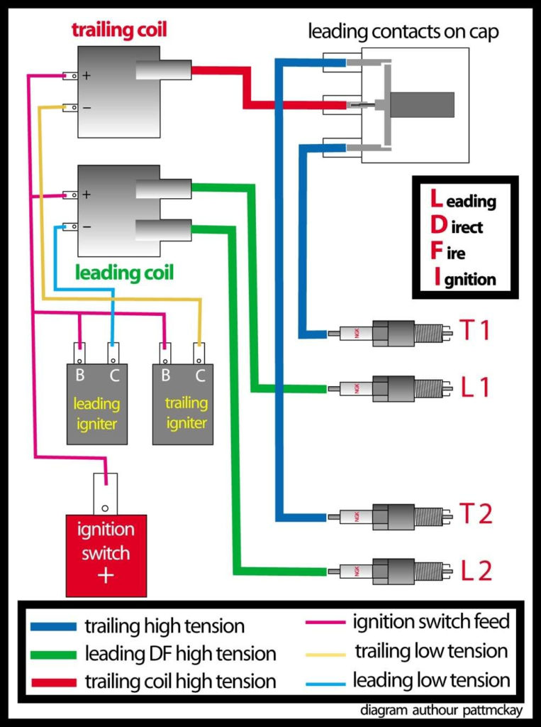
Terminals for coil
The terminology used to determine the kind and model of an ignition coil is the most important thing. An understanding of the basic wiring diagram for ignition will reveal a variety of terminals and connections. Each coil comes with its own operating voltage. To determine the type of coil you own the first step is to determine the voltage at S1, which is the primary terminal. S1 should also be checked for resistance in order to identify if the coil is a Type B, B, or A coil.
The coil’s low-tension end must be connected with the chassis positive. This is the wiring diagram you will see in the wiring diagram. The high tension side provides positively directly to the spark plugs. For suppression purposes, the coil’s body metal must be connected with the chassis. It is not required for electrical use. The ignition wiring diagram will also indicate the connections of the positive coil’s terminals. You may find an issue with your ignition coil that is easily identified by scanning it at an auto parts retailer.
The black-and-white-striped wire from the harness goes to the negative terminal. The white wire also is black with a trace, and connects to the positive terminal. The black wire is connected to the contact breaker. You can examine the connections with a paperclip to take the wires out from the housing. It is also important to ensure that the terminals aren’t bent.
Accessory terminals
The ignition wiring diagrams show the different wires used to power different components. Each component has four distinct connections that are color coded. The red color is used for accessories and yellow is for the battery, while green is the solenoid for starters. The “IGN” terminal is used to start the car , and also to operate the wipers, as well as other operating features. The diagram illustrates how to connect ACC or ST terminals as well as the rest.
The terminal BAT is where the battery is. The electrical system cannot start without the battery. A dead battery could cause the switch to not come on. It is possible to look up the wiring diagram of your car to see where the batteries of your car are situated. The accessory terminals of your vehicle connect to the battery and the ignition switch. The BAT terminal is connected with the battery.
Some ignition switches come with an accessory position. This lets users connect their outputs to another location without having to turn on the ignition. Sometimes, customers want to utilize an additional output independent of the ignition. The auxiliary output can be utilized by wiring the connector with the same colors as the ignition, and then connecting it to the ACC terminal of the switch. This is a great convenience feature however there’s a differentiator. The majority of ignition switches have an ACC position if the car is in the ACC however, they will be in the START position when the car is in IGN.
Gallery of Ignition Wiring Harness Diagram
Gallery of Ignition Wiring Harness Diagram


