Massey Ferguson Ignition Switch Wiring Diagram – First, we will examine the various types of terminals on the ignition switch. They include terminals for the Ignition switch, Coil, and Accessory. Once we know the purpose of each kind of terminal, we can then identify the various components of the ignition wiring. We will also discuss what functions are available for the Ignition switch and the Coil. Then we’ll proceed to the Accessory Terminals.
The ignition switch’s terminals
An ignition switch has three different switches that direct the battery’s power to various destinations. The first switch powers the choke. The second switch controls the ON/OFF switch of the ignition switch. Every manufacturer has its own color-coding system, which we’ll go over in a separate article. OMC uses this procedure. The connector permits the attachment of a speedometer the ignition switch.
Although the majority of ignition switch terminals aren’t original, the numbering for each one may not be in line with the diagram. You should first check the continuity of the wires to determine if they’re plugged into the correct ignition switch. This can be checked using a simple multimeter. When you are satisfied with the integrity of the wires, you can connect the new connector. If your vehicle has an original factory-supplied ignition switch (or a wiring loom) The wiring loom might differ from that of your vehicle.
Understanding how ACC outputs connect to the other outputs inside your car is vital. The ACC and IGN terminals are the default connections on the ignition switch. the START and IGN terminals are the principal connections to the stereo and radio. The ignition switch’s function is for turning the car’s engine on and off. On older cars the ignition switch’s terminals are marked with the letters “ACC”, and “ST” (for the individual magnetic wires).
Terminals for coil
The terms used to define the model and type of an ignition coil is the first thing. A basic ignition wiring layout will reveal a variety of connections and terminals. You must determine the type of coil that you have by testing the voltage at the primary terminal S1. S1 should also be checked for resistance to determine whether it’s an A, Type B or A coil.
The coil with low tension must be connected to the chassis’ less. This is the wiring diagram you will find in the diagram of wiring. The high-tension component supplies positive directly to the spark plugs. The aluminum body of the coil has to be connected to the chassis for suppression, but it isn’t electrically required. The diagram for the ignition wiring will also show you how to connect the negative and positive coil’s terminals. In certain instances it is recommended to conduct a scan at your local auto parts store will be able to diagnose the malfunctioning ignition coils.
The black-and-white-striped wire from the harness goes to the negative terminal. The positive terminal is connected to the white wire and the trace in black. The black wire goes to the contact breaker. To verify the connection, use a paperclip or a pencil to pull them out of the plug housing. Be sure the terminals aren’t bent.
Accessory terminals
Diagrams of ignition wiring show the wiring used in the vehicle’s power supply. There are usually four colored terminals that correspond to each component. The red color is used for accessories while yellow is the battery, while green is the solenoid for starters. The “IGN” terminal allows you to start the car, manage the wipers, and any other operation features. The diagram illustrates the connection of the ACCas well as ST terminals.
The terminal BAT is where the battery is. The battery is vital for the electrical system to start. In addition, the switch will not start. You can view your wiring diagram to figure out where your car’s batteries are situated. The ignition switch and battery are connected by the accessory terminals. The BAT terminal is connected to the battery.
Certain ignition switches come with an accessory setting where users can alter their outputs and control them without having to turn on the ignition. Sometimes, a customer wants to make use of the auxiliary output separately from the ignition. The auxiliary output can be utilized by wiring the connector with the same colors as your ignition, and then attaching it to the ACC terminal of the switch. While this is an excellent feature, there’s one crucial distinction. A majority of ignition switches feature the ACC position when your car is in ACC mode, and a START position when the switch is in IGN.
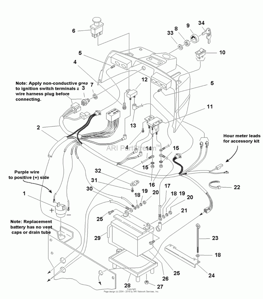
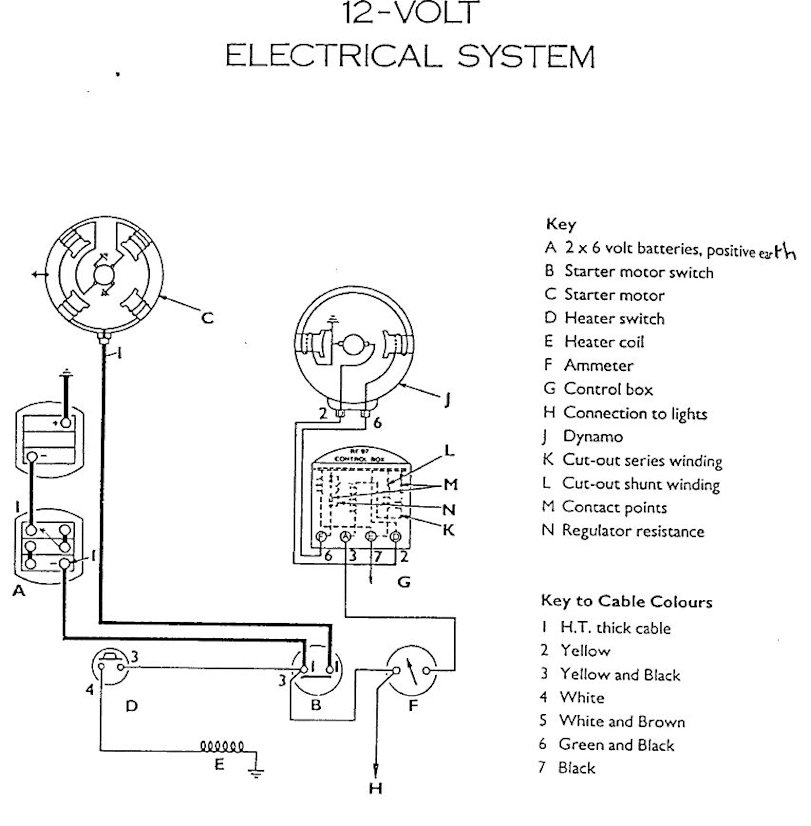
Gallery of Massey Ferguson Ignition Switch Wiring Diagram
Gallery of Massey Ferguson Ignition Switch Wiring Diagram


