Ignition Wiring Mercruiser 3.0 Wiring Diagram – In the beginning, we’ll take a look at the various kinds of terminals in the ignition switch. These terminals comprise the Ignition switch and Coil along with the Accessory. Once we know what these kinds of terminals are used for, we will proceed to determine the various parts of the Ignition Wiring Mercruiser 3.0 Wiring Diagram. We will also discuss the roles of the Ignition switch as well as the Coil. Following that, we’ll shift our attention to Accessory terminals.
Terminals for the ignition switch
An ignition switch is comprised of three switches. They supply the battery’s voltage to different locations. The choke is powered by the first switch. The third switch regulates the ON/OFF switch of the ignition switch. Different manufacturers employ different colors for different conductors. This is described in another article. OMC uses this method. The connector allows for the connection of a speedometer to the ignition switch.
While most ignition switch terminals may not be authentic, the numbering of each might not be consistent with the diagram. Check the continuity of the wires first to ensure they’re connected correctly to the ignition switch. A multimeter is a good instrument to verify the continuity. After you have verified the continuity of the wires you can then connect the connector. If your vehicle has an installed ignition switch the wiring diagram will differ.
First, understand the differences between ACC and the auxiliary outputs. The ACC and IGN connectors are the standard connections of the ignition switch. Although the START, IGN, and ACC terminals are the primary connections for the radio or stereo, the START/IGN terminals are the primary ones. The ignition switch’s function is for turning the car’s engine on and off. On older cars, the ignition switch terminals are marked with the letters “ACC” as well as “ST” (for the individual magnet wires).
Terminals for coil
The terminology used to determine the kind and model of the ignition coil is the first thing. In a basic diagram of the wiring for ignition there are a number of different terminals and connections, including two primary and two secondary. The coils come with a distinct operating voltage. The initial method of determining what type you’re using is to test the voltage at S1, the main terminal. S1 must be checked for resistance to identify if the coil is type A, B and/or C.
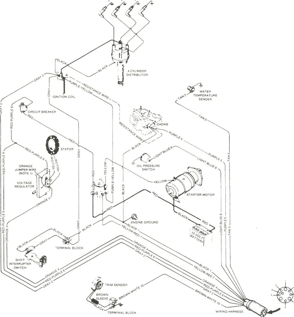
The negative of the chassis must be connected to the low-tension side. This is exactly what you can see in the wiring diagram. The high-tension supply supplies the spark plugs with positive electricity directly. The aluminum body of the coil has to be linked to the chassis for suppression but isn’t required. The wiring diagram for ignition will also show the connection of the positive coil terminals. In some instances you’ll discover that a malfunctioned ignition coil is identified by scans in an auto parts store.
The black-and-white-striped wire from the harness goes to the negative terminal. The other white wire has a black color and connects to the negative terminal. The black wire connects with the contact breaker. If you’re unsure of the connection between the twowires, use an old paper clip to take them from the housing of the plug. It’s also crucial to ensure that the terminals do not bend.
Accessory terminals
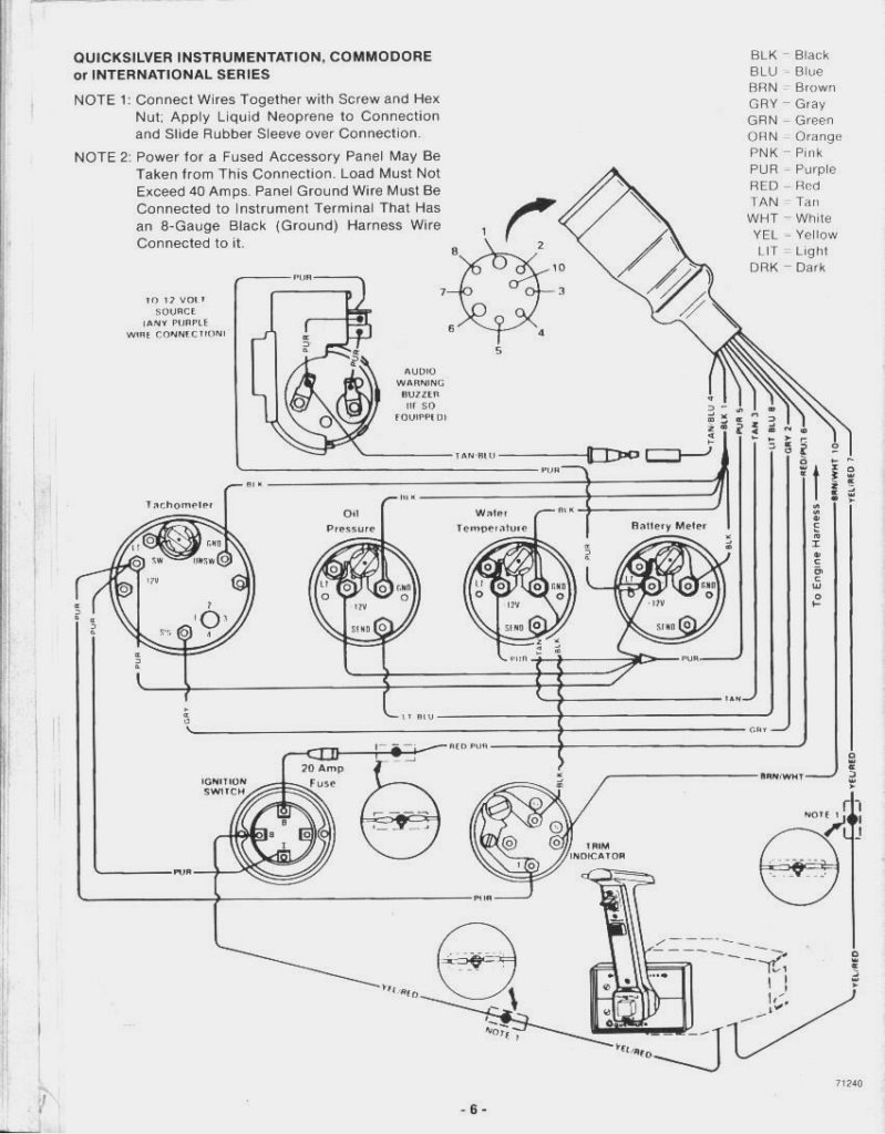
The diagrams for ignition wiring depict the wires used in the power supply of the vehicle. There are generally four colors of terminals connected to each part. The accessories are colored red and the battery yellow the starter solenoid is green. The “IGN terminal” is used to provide power to the wipers and other operating features. The diagram illustrates the connection to the ACC- and ST terminals.
The terminal BAT is the connection for the battery. The electrical system will not start when the battery isn’t connected. The switch will not turn off if the battery isn’t present. It is possible to look up the wiring diagram of your car to see the location of your car’s batteries. placed. The accessory terminals in your car are connected with the battery and the ignition button. The BAT connector connects to your battery.
Some ignition switches come with an additional position. This lets users access their outputs from a different place without having to turn on the ignition. Sometimes, customers wish to utilize the auxiliary output separately from the ignition. To use the additional output, wire the connector with identical colors to the ignition connecting it to the ACC terminal on the switch. This is a useful feature, but there is one important distinction. Most ignition switches will have an ACC position if the car is in ACC however they will be in the START position when the vehicle is IGN.
Gallery of Ignition Wiring Mercruiser 3.0 Wiring Diagram
Gallery of Ignition Wiring Mercruiser 3.0 Wiring Diagram


