Kawasaki Ignition Wiring Diagram – Let’s first examine the different types and functions of the terminals found on the ignition switches. They are the terminals used that are used for Coil, Ignition Switch, and Accessory. Once we know the purpose of each kind of terminal, it is possible to identify the various components of the ignition wiring. We’ll also be discussing the roles of the Ignition switch, as well as the Coil. After that, we will focus on the accessories terminals.
Terminals for ignition switches
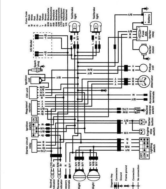
Three switches can be found in an ignition switch. Each of these three switches is able to feed the battery’s voltage to several different places. The choke is powered by the first switch. The second switch controls the ON/OFF switch of the ignition switch. Different manufacturers have distinct color-coding systems that correspond to the conductors. OMC uses this method. There is a connector inside the ignition switch to allow attaching a Tachometer.
While most ignition switch terminals may not be authentic, the numbering of each might not be consistent with the diagram. You should first check the continuity of the wires to ensure that they are connected to the ignition switch correctly. This can be done with a cheap multimeter. Once you are satisfied that all wires are in good continuity and you are able to connect the new connector. If you are using an ignition switch supplied by the manufacturer the wiring loom may be different from that you have in your car.
It is important to know the differences between the ACC and the auxiliary outputs. The ACC terminals and IGN terminals function as the primary connections to your ignition switch. The START and IGN connections are the main connections for radio and stereo. The ignition switch turns the engine of your car ON and off. On older cars, the ignition switch terminals are identified with the alphabets “ACC” as well as “ST” (for the individual magnet wires).
Coil terminals
Understanding the terms is the first step in determining which type of ignition coil you’ve got. A basic diagram of the wiring will provide you with a range of connections and terminals. You need to determine the kind of coil you have by testing the voltage on the primary terminal, called S1. To determine whether it’s an A, C or B coil, it is recommended to also test the resistance on S1’s.
The negative end of the chassis must be connected to connect the coil’s low-tension end. This is also the ground in the wiring diagram for ignition. The high tension part supplies positive power directly to the spark plugs. The aluminum body of the coil needs to be linked to the chassis to prevent it from being smothered but isn’t required. The wiring diagram for the ignition will explain how to connect the two terminals of the positive and negative coils. You may find an ignition coil problem that can be easily diagnosed by scanning it in an auto parts retailer.
The black-and-white-striped wire from the harness goes to the negative terminal. The negative terminal is served by the black trace that’s connected to the white wire. The black wire goes to the contact breaker. It is possible to remove the black wire from the housing of the plug with a paper clip in case you are uncertain about the connection. Make sure the terminals aren’t bent.
Accessory terminals
The ignition wiring diagrams illustrate the different wires that provide power to the various parts of the vehicle. In general, there are four different color-coded terminals for each component. For accessories, red is the starter solenoid’s color, yellow is for battery, and blue for accessory. The “IGN” terminal is used for starting the vehicle, controlling the wipers and other functions. The diagram shows the connections of the ACC- and ST terminals.
The battery is connected to the terminal called BAT. The electrical system can’t be started without the battery. Furthermore the switch isn’t turned on. It is possible to view your wiring diagram to determine where the batteries of your car are placed. The ignition switch is connected to the battery of your car. The BAT terminal is connected to the battery.
Certain ignition switches have an additional position. This lets users access their outputs from a different place without the ignition. Some customers might want to utilize the auxiliary input independently of the ignition. The auxiliary output can be used to connect the connector with the same colors as your ignition, and then connecting it to the ACC terminal of the switch. This is a useful feature, but there is an important distinction. Some ignition switches are programmed to have an ACC position once the car is in the ACC position. They also will be in the START position after the vehicle has been moved into the IGN position.
Gallery of Kawasaki Ignition Wiring Diagram
Gallery of Kawasaki Ignition Wiring Diagram


