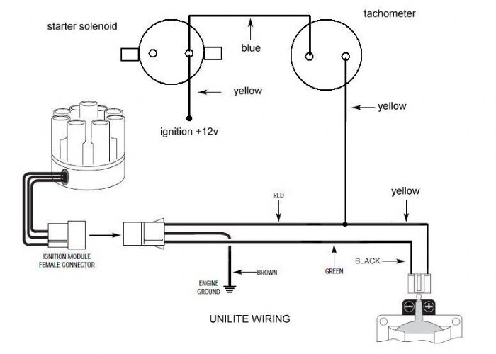
Mallory Unilite Ignition Wiring Diagram – We will first examine the different types of terminals on the ignition switch. These are terminals for the Ignition, Coil, or Accessory. Once we have established the purpose of these terminals are then we can discover the various components of the Mallory Unilite Ignition Wiring Diagram. We will also cover the different functions of the Ignition Switch and the Coil. Then, we’ll turn our attention to the Accessory terminals.
Terminals for ignition switches
An ignition switch contains three different switches that direct the battery’s current to different locations. The first switch powers the choke. The second switch is responsible for the ON/OFF function of the ignition switch. Different manufacturers use their own color-coding systems for the different conductors, which is explained in a different article. OMC uses this procedure. The adapter is attached to the ignition switch, allowing for the addition of the tachometer.
Even though some of the ignition switch terminals might not be original, the numbers of each may not match the diagram. It is important to first verify the integrity of the wires to see if they are plugged into the correct ignition switch. This can be checked using a cheap multimeter. After you’re satisfied with the integrity of the wires, you can install the new connector. If your vehicle has an original ignition switch supplied by the factory (or a wiring loom), the wiring loom might differ from that of your vehicle.
Understanding how ACC outputs are connected to the auxiliary outputs of your car is vital. The ACC, IGN and START terminals are the primary connections to the ignition switch. They are also the primary connections to your radio and stereo. The ignition switch turns the engine of your car ON and off. The terminals of the ignition switch on older cars are labeled with the initials “ACC” and “ST” (for individual magneto wires).
Terminals for coil
Understanding the terms utilized is the first step towards determining what kind of ignition coil you need. A basic ignition wiring layout will provide you with a range of terminals and connections. Each coil is operating at a certain voltage. The first step to determine the kind you’re dealing with is to test the voltage on S1, or the primary terminal. S1 should be checked for resistance to determine if the coil belongs to type A, B and/or C.
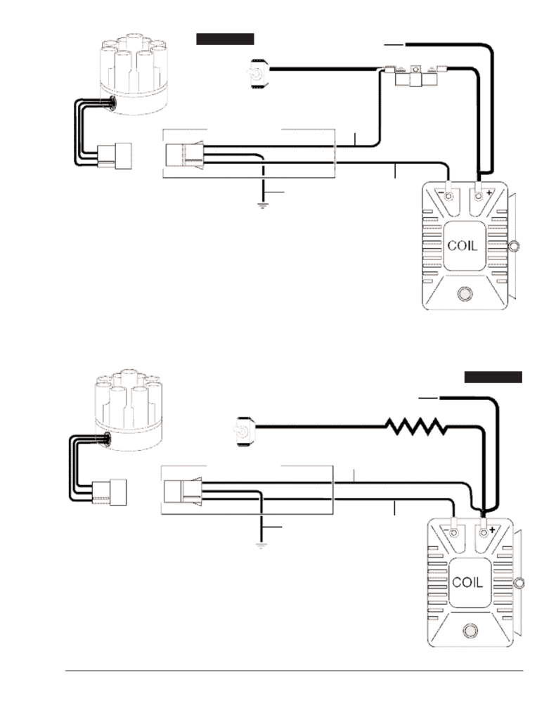
The low-tension coil side must be connected at the chassis’s less. This is the ground on the diagram of ignition wiring. The high-tension side delivers the positive power direct to the spark plugs. The body of the coil has to be connected to the chassis to prevent it from being smothered, but it is not electrically necessary. It is also possible to see the connections of the positive and the negative coil’s terminals on an ignition wiring diagram. In certain cases scanning your local auto parts store will help identify defective ignition coils.
The black-and-white-striped wire from the harness goes to the negative terminal. Positive terminal gets the second white wire, which is black in its trace. The black wire is connected to the contactbreaker. If you’re unsure of the connection between both, you can use a paper clip to remove them from the plug housing. Also, make sure to verify that the connections have not been bent.
Accessory terminals
The diagrams for ignition wiring illustrate the wires that are used in the power supply of the vehicle. In general there are four distinct colors-coded terminals that are used for each component. The accessories are colored red, the battery is yellow and the starter solenoid green. The “IGN” terminal is used to start the car and operate the wipers as well as other operational features. The diagram shows how to connect ACC or ST terminals, and other.
The terminal BAT is where the battery is. The electrical system won’t start when the battery isn’t connected. In addition, the switch will not begin to turn on. If you’re not sure of where your car’s battery is situated, look at your wiring diagram to figure out the best way to find it. The ignition switch and battery are connected through the accessory terminals. The BAT connector connects to your battery.
Some ignition switches come with an additional position. It allows users to access their outputs from a different location without having to turn on the ignition. Some customers might want to utilize the auxiliary output separately from the ignition. You can utilize the auxiliary input by connecting the connector to the ACC terminal. This feature is convenient however it does have one major distinction. Most ignition switches will be in an ACC position if the car is in the ACC however they’ll be in the START position if the car is in IGN.
Gallery of Mallory Unilite Ignition Wiring Diagram
Gallery of Mallory Unilite Ignition Wiring Diagram


