Yamaha 115 Outboard Ignition Switch Wiring Diagram – Let’s first take a look at the different types of terminals on the ignition switch. They include terminals for the Ignition switch, Coil, and Accessory. When we have a clear understanding of the purpose of each terminal, we can then determine the components of the ignition wiring. We’ll also discuss the functions and the Coil. Following that, we will discuss the Accessory Terminals.
Terminals for the ignition switch
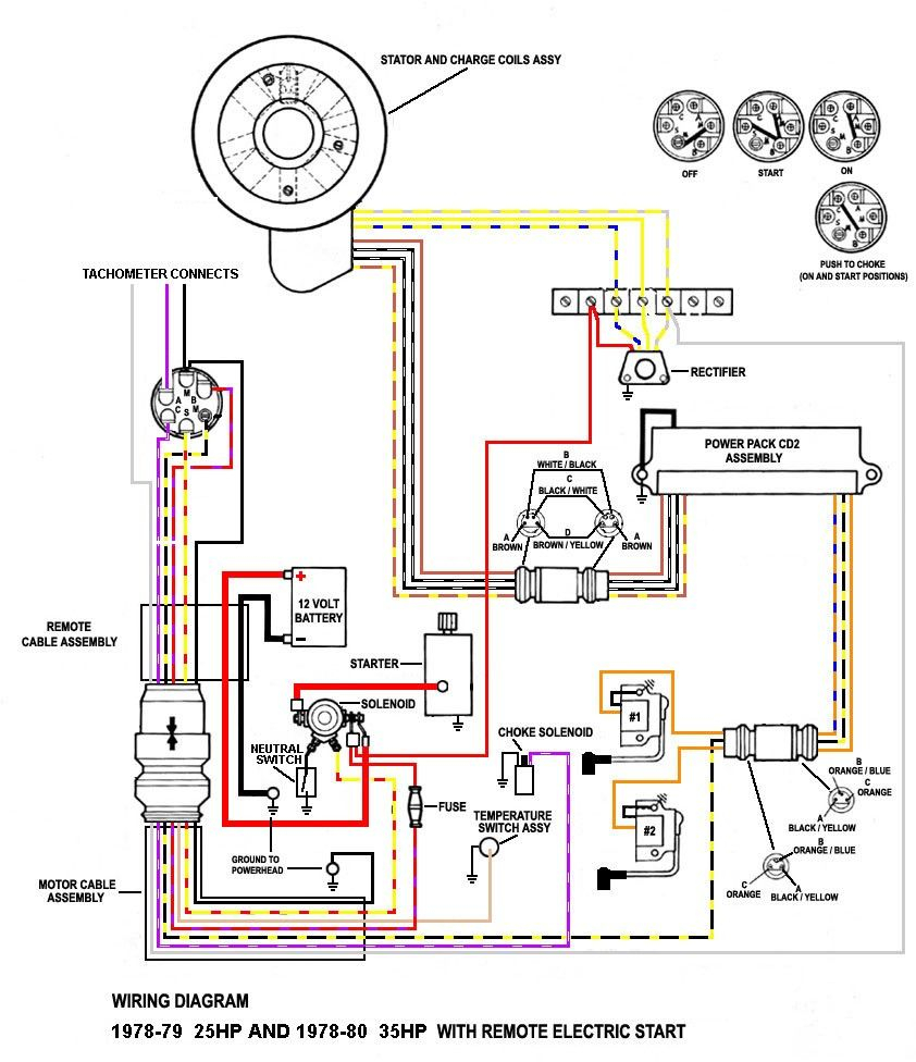
The ignition switch is comprised of three switches that supply the battery’s current to various destinations. The first switch is utilized to turn on the choke by pushing it, and another switch controls the ON/OFF position. Different manufacturers employ different color codes for different conductors. This is described in a separate article. OMC uses the same method. The ignition switch comes with a connector for adding the tachometer.
While most ignition switch terminals may not be original, the numbers for each may not match the diagram. Check the continuity of the wires to determine if they’re connected to the correct ignition switch. A multimeter is an excellent tool to check the continuity. Once you are satisfied with the integrity of the wires, you can connect the new connector. The wiring loom of a factory-supplied ignition system switch differs.
Knowing how the ACC outputs are connected to the other outputs of your car is essential. The ACC and IGN connectors are the standard connections for your ignition switch. The START, IGN, and ACC terminals are primary connections to the radio or stereo, the START/IGN terminals are the main ones. The ignition switch is the one that turns the engine of your car to and off. The terminals on older cars ignition switches are marked by “ACC” and ST (for the individual magneto wires).
Coil terminals
The terminology used to determine the kind and model of an ignition coil is the most important thing. A basic diagram of the wiring will show you a number of terminals and connections. Each coil has an operating voltage. The first step to determine the kind of coil you have is to check the voltage on S1, or the primary terminal. S1 must be examined for resistance to determine if the coil belongs to type A, B or C.
The chassis’ negative end should be connected to to the coil’s lower-tension end. This is the ground in the diagram of the ignition wiring. The high-tension side provides positive direct to the sparkplugs. The metal body of the coil needs to connect to the chassis for suppression purposes however it isn’t electrically necessary. The diagram of the ignition wiring will also demonstrate the connections between the negative and positive coil’s terminals. In certain instances, a scan at your local auto parts shop will be able to diagnose malfunctioning ignition coils.
The black-and-white-striped wire from the harness goes to the negative terminal. The negative terminal is served by the trace in black that’s joined to the white wire. The black wire connects to the contact breaker. If you’re not sure about the connection between the two, try using a paper clip to remove them from the housing of the plug. Make sure you check that the terminals aren’t bent.
Accessory terminals
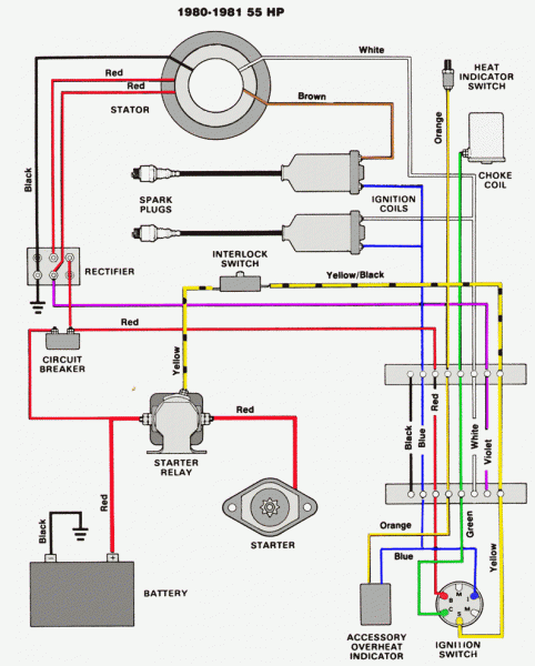
The wiring diagrams for the ignition show the various wires that power the various components of the vehicle. There are generally four colored terminals that correspond to each component. To identify accessories, red is the starter solenoid’s color, blue for battery and blue for accessories. The “IGN terminal” is used to power the wipers as well as other operating functions. The diagram below shows how to connect both the ACC terminal as well as the ST terminals to the other components.
The terminal BAT connects the battery to the charger. The electrical system is not able to begin without the battery. Also, the switch won’t turn on without the battery. If you don’t know the exact location where the battery in your car is situated, you can examine your wiring diagram to see the best way to find it. The accessory terminals in your vehicle are connected to the battery and the ignition button. The BAT terminal is connected with the battery.
Some ignition switches feature a separate “accessory” location, which allows users can control their outputs without using the ignition. Customers may want to utilize the auxiliary output independently of the ignition. It is possible to use the auxiliary input by connecting the connector to the ACC terminal. This feature of convenience is fantastic, but there is one distinction. Most ignition switches are configured to operate in the ACC position when the car is in the ACC position, but they’re set to the START position when the car is in the IGN position.
Gallery of Yamaha 115 Outboard Ignition Switch Wiring Diagram
Gallery of Yamaha 115 Outboard Ignition Switch Wiring Diagram


