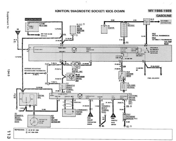
Mercedes W124 Ignition Switch Wiring Diagram – First, let’s look at the different terminals used on the ignition switch. These are the terminals for the Ignition, Coil, or Accessory. Once we know the purpose of each terminal, we are able to determine the components of the ignition wiring. We will also cover the functions of both the Ignition Switch and the Coil. We will then turn our attention towards the accessory terminals.
The terminals of the ignition switch
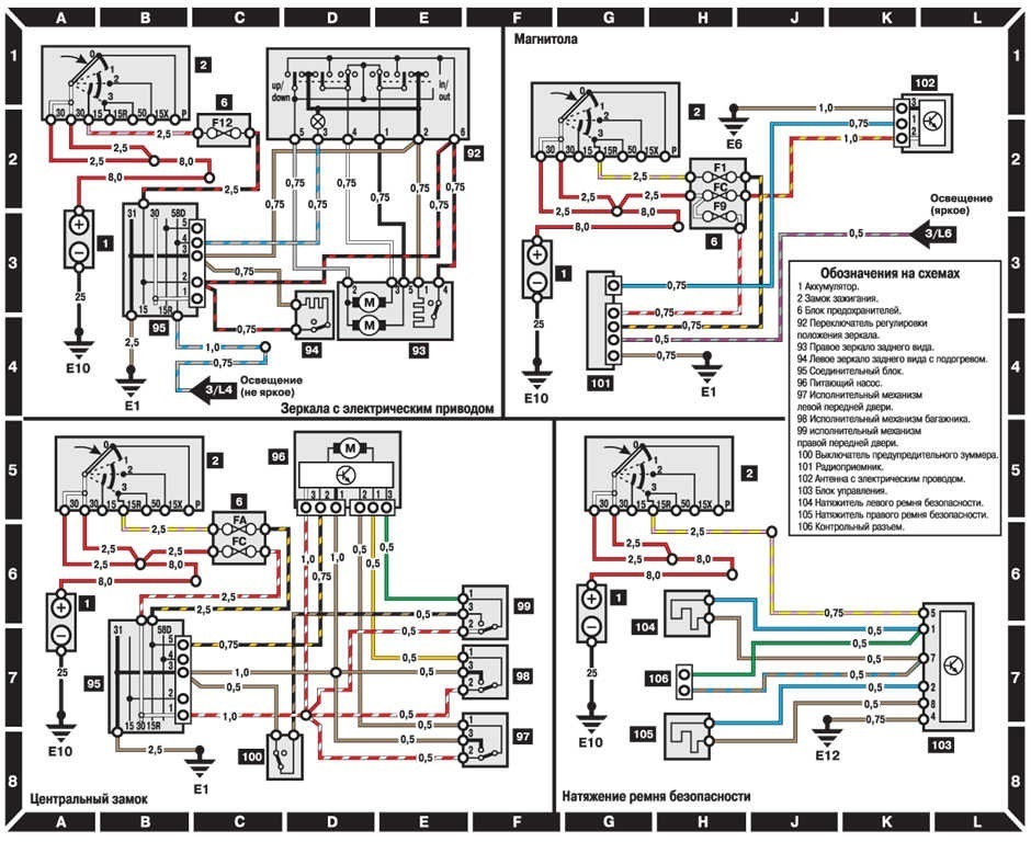
Three switches are found on an ignition switch. Each of these switches is able to feed the battery’s voltage to several different destinations. The first is used to power the choke through pushing it, while another switch controls the ON/OFF position. Different manufacturers use various color codes for the different conductors. This is explained in a different article. OMC follows the same system. This connector allows the attachment of a speedometer to the ignition switch.
While some ignition switch terminals do not have the original design The numbering might not match the diagram. Verify the continuity of the wires first to make sure they’re properly connected to the ignition switch. This can be done with a cheap multimeter. Once you’ve verified the continuity of the wires you can connect the connector. The wiring loom in a factory-supplied ignition system switch is different.
To connect the ACC outputs to the auxiliary outputs of your car, you need first know the way these two connections function. The ACC terminals as well as the IGN terminals serve as the primary connections to the ignition switch. The START and IGN connections are the most important connections for radio and stereo. The ignition switch regulates the engine in your car. The terminals of older vehicles’ ignition switches are labeled with “ACC” and ST (for individual magneto wires).
Terminals for coil
Understanding the terminology is the first step towards finding out what kind of ignition coil you own. A simple diagram of the wiring will show a variety of terminals and connections, which include two primary terminals and two secondary. You need to determine the type of coil that you own by examining the voltage at the primary terminal, S1. You should also examine S1 for resistance in order to determine if it’s an A, B, or C coil.
The coil with low tension must be connected to the chassis’ less. It is also the ground for the diagram of ignition wiring. The high-tension part provides the spark plugs with positive. It is necessary for the purpose of suppression that the body of the coil’s metal be connected to its chassis, however it isn’t essential. The wiring diagram of the ignition will demonstrate how to connect the terminals of the positive or negative coils. Sometimes, an inspection at an auto parts shop can identify a problem with the ignition wire.
The black-and-white-striped wire from the harness goes to the negative terminal. The white wire also is black with a trace, and connects to the positive terminal. The black wire connects to the contact breaker. You can take the black wire from the housing of the plug with a paper clip If you’re unsure of the connections. Be sure that the terminals aren’t bent.
Accessory terminals
The ignition wiring diagrams illustrate the different wires that power the various components of the car. There are generally four color-coded terminals that correspond to each component. Red is used to indicate accessories, yellow the battery and green is the starter solenoid. The “IGN terminal” is used to power the wipers along with other operational functions. The below diagram shows how to connect both the ACC terminal and ST terminals to other components.
The terminal BAT connects the battery to the charger. The electrical system is not able to start without the battery. Furthermore, the switch won’t begin to turn on. A wiring diagram can show you the location of the battery in your car. The accessory terminals of your vehicle connect to the battery as well as the ignition switch. The BAT terminal is connected to the battery.
Certain ignition switches come with the “accessory” position that allows users to regulate their outputs without having to use the ignition. Sometimes, users want to use an auxiliary output independent of the ignition. The auxiliary output is connected by wiring the connector with the same colors as the ignition and connecting it to the ACC terminal of the switch. This is an excellent feature, however there’s an important difference. Most ignition switches are designed to display an ACC status when the car is at the ACC or START positions.
Gallery of Mercedes W124 Ignition Switch Wiring Diagram
Gallery of Mercedes W124 Ignition Switch Wiring Diagram


