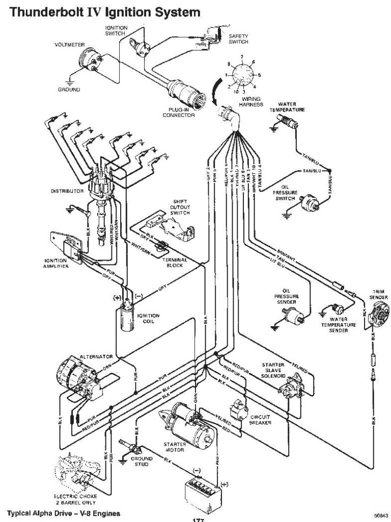
Mercruiser 5.7 Ignition Wiring Diagram – The first step is to take a look at the different kinds of terminals for the ignition switch. They include terminals that are used for Coil, Ignition Switch, and Accessory. Once we know what these types of terminals are used for We will then identify the different parts of the Mercruiser 5.7 Ignition Wiring Diagram. We will also discuss the roles of the Ignition switch, as well as the Coil. Following that, we will move on to the Accessory Terminals.
The ignition switch’s terminals
Three switches can be found on the ignition switch. Each of these three switches transmits the battery’s current to various locations. The first switch is the one that supplies power to the choke, while the second switch controls the ON/OFF status of the ignition switch. Different manufacturers use different colors for various conductors. This is explained in a different article. OMC uses this system. An adapter is included on the ignition switch to allow the installation of the tonometer.
Although the majority of ignition switch terminals aren’t original, the numbers for each may not match the diagram. Before plugging into the ignition switch be sure to test the continuity. This can be done with a simple multimeter. When you are satisfied with the continuity of the wires you can install the new connector. If your vehicle has an original factory-supplied ignition switch (or an electrical loom) The wiring loom will differ from the one in your car.
Before connecting the ACC outputs to your car’s auxiliary outputs it is crucial to understand the basics of these connections. The ACC, IGN and START terminals are the default connections to the ignition switch. They also serve as the primary connections to your radio and stereo. The ignition switch is the one that controls the engine of your car. The terminals on older cars ignition switches are identified by “ACC” as well as ST (for specific magneto wires).
Coil terminals
Understanding the terminology used is the first step towards determining the kind of ignition coil to choose. An understanding of the basic wiring diagram for ignition will provide you with a range of terminals and connections. You need to determine the type of coil that you own by examining the voltage on the primary terminal S1. To determine if the coil is an A, C or B coil, you must also test the resistance on S1’s.
The chassis’ negative needs to be connected to the side of low-tension. This is the base of the wiring for ignition. The high-tension part supplies positive direct to the sparkplugs. It is necessary to suppress the body of the coil’s metal be connected to its chassis however, it is not necessary. The wiring diagram for ignition will also outline the connections of the positive coil terminals. You may find an ignition coil problem that is easily identified by scanning it in an auto parts retailer.
The black-and-white-striped wire from the harness goes to the negative terminal. The positive terminal also receives a white wire that includes a black trace. The black wire connects to the contact breaker. You can remove the black wire from the housing of the plug by using a paperclip in case you are uncertain about the connection. It’s also crucial to ensure that the terminals don’t bend.
Accessory Terminals
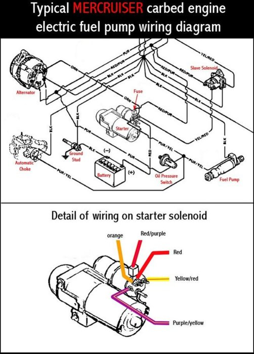
The ignition wiring diagrams illustrate the different wires used to provide power to the various parts of the car. Each component is equipped with four distinct color-coded connections. The red symbol represents accessories, yellow is for the battery and green is for the starter solenoid. The “IGN terminal lets you start the car, manage the wipers, and any other functions. The diagram illustrates how to connect ACC or ST terminals, and other.
The terminal BAT is the connection to the battery. The electrical system won’t start if the battery isn’t connected. A dead battery can make the switch not come on. It is possible to view your wiring diagram to determine where your car’s batteries are located. The ignition switch and battery are connected by the accessory terminals. The BAT terminal is connected with the battery.
Certain ignition switches have an accessory position where users can adjust their outputs and manage them without the need to use the ignition. In some cases, users may want to use the auxiliary input separately from the ignition. The auxiliary output could be utilized by wiring the connector with the same colors as your ignition, and then attaching it to the ACC terminal of the switch. Although this is a useful feature, there’s one crucial distinction. A majority of ignition switches feature an ACC position when your car is in ACC mode, and a START position when the switch is in IGN.
Gallery of Mercruiser 5.7 Ignition Wiring Diagram
Gallery of Mercruiser 5.7 Ignition Wiring Diagram


