Race Car Ignition Wiring Diagram – We’ll begin by looking at different types of terminals in an ignition switch. These terminals comprise the Ignition switch and Coil along with the Accessory. Once we have identified the purpose of these terminals and what they do, we can then identify the different parts in the ignition wiring. In addition, we will discuss the roles of both the Ignition Switch and Coil. After that, we will concentrate on the accessories terminals.
Terminals for ignition switches
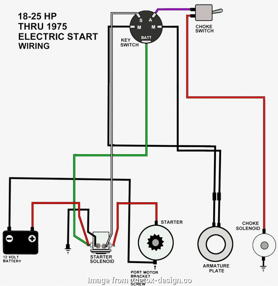
An ignition switch is composed of three different switches. They are responsible for feeding the battery’s power to several destinations. The first switch powers the choke. The third switch regulates the ON/OFF switch of the ignition switch. Different manufacturers have different color-coding systems to identify different conductors. We’ll discuss this in a different article. OMC utilizes this system. Connectors can be attached to the ignition switch in order to include a digital Tachometer.
Even though some of the ignition switch terminals may not be original, the numbers of each one might not be in line with the diagram. To ensure that the wires are properly plugged in to the switch it is recommended to check their continuity. This can be accomplished using a cheap multimeter. After you’re satisfied with the quality of the connection it’s time to connect the new connector. If you’re using a factory-supplied ignition switch the wiring loom may be different from that used in your vehicle.
In order to connect the ACC outputs to the auxiliary outputs of your car, you’ll need to understand how these two connections work. The ACC/IGN connections function as the default connection on the ignition switch. The START/IGN terminals are connected to the stereo or radio. The ignition switch is responsible for turning the car’s engine on and off. Older cars have the ignition switch’s terminals that are labeled “ACC” or “ST” (for individual magnetowires).
Terminals for Coil
The terminology used to determine the kind and model of an ignition coil is the most important thing. A basic ignition wiring layout will show you a number of connections and terminals. You need to determine the type of coil you own by examining the voltage at the primary terminal, S1. To determine whether it’s a Type A, C or B coil, you must also test S1’s resistance.
The low-tension end of the coil should be connected to the chassis”negative. This is also the ground for an ignition wiring diagram. The high-tension side connects the spark plugs to a positive. The metal body of the coil needs to be connected to the chassis to prevent it from being smothered, but it is not electrically required. The diagram of the ignition wiring will also show the connections of the positive coil’s terminals. Sometimes, a visit to an auto part store can identify a problem with the ignition wire.
The black-and-white-striped wire from the harness goes to the negative terminal. The terminal that is negative is served by the trace in black that’s attached to the white wire. The black wire connects to the contactbreaker. You can examine the connections using a paperclip to remove the wires of the housing. Make sure that the connectors don’t bend.
Accessory terminals
Diagrams of ignition wiring depict the wiring used to provide power to various components of the vehicle. Each component is equipped with four distinct color-coded connections. To identify accessories, red is the starter solenoid’s color, yellow for battery and blue for accessory. The “IGN” terminal is utilized to turn on the car, operate the wipers and other functions. The diagram shows the connection of the ACCas well as ST terminals.
The terminal BAT connects the battery to the charger. Without the battery, the electrical system does not begin. Additionally, the switch won’t start. To locate your car’s battery examine the wiring diagram. The ignition switch is connected to the battery of your car. The BAT terminal is connected to the battery.
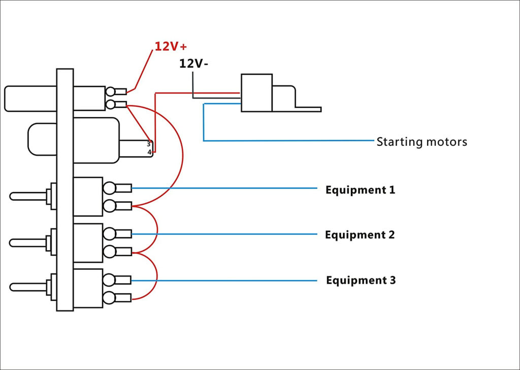
Certain ignition switches have an accessory setting where users can adjust their outputs and manage them without having to turn on the ignition. Some customers want the output of the auxiliary to be operated independently of the ignition. The auxiliary output can be used by wiring the connector with the same colors as the ignition and attaching it to the ACC terminal of the switch. While this is a convenient feature, there’s one significant difference. Many ignition switches have an ACC position when the car is in the ACC mode, and a START position when it is in IGN.
Gallery of Race Car Ignition Wiring Diagram
Gallery of Race Car Ignition Wiring Diagram


