Mgb Ignition Switch Wiring Diagram – The first step is to examine the different types of terminals that are used on the ignition switch. These terminals include the Ignition switch as well as the Coil along with the Accessory. When we have a clear understanding of the purpose of each terminal, we are able to determine the components of the ignition wiring. Then, we will discuss the functions as well as the Coil. After that, we will focus on the accessories terminals.
Terminals for ignition switches
An ignition switch is comprised of three switches. They transmit the voltage of the battery to different places. The first switch provides power to the choke when pushed, and the second is the ignition switch’s ON/OFF position. Different manufacturers have different color-coding systems that correspond to the conductors. OMC follows this scheme. The connector allows for the connection of a speedometer to the ignition switch.
While many ignition switch terminals don’t come in original form however, the numbers may not match that of the diagram. Before you plug into the ignition switch, make sure to check the continuity. You can do this with a simple multimeter. Once you are satisfied with the integrity of the wires, install the new connector. If your car has an original ignition switch supplied by the factory (or wiring loom) the wiring loom might differ from that in your vehicle.
For connecting the ACC outputs to the auxiliary outputs on your car, you’ll need first know how these two connections work. The ACC and IGN terminals are the default connection on your ignition switch, and the START and IGN terminals are the principal connections for radio and stereo. The ignition switch is the one that controls the engine of your car. Older cars are identified with the alphabets “ACC”, “ST”, (for individual magneto cables) on their ignition switch terminals.
Terminals for coil
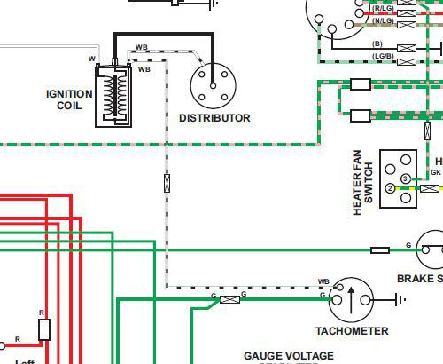
The language used to decide the kind and model of the ignition coil is the most important thing. A basic diagram of the wiring will provide you with a range of terminals and connections. The coils are equipped with a particular operating voltage. The initial method of determining what type you have will involve testing the voltage on S1, the main terminal. To determine if the coil is an A, C or B coil, you must also test the resistance on S1’s.
The low-tension side of the coil must be connected to the chassis”negative. This is the ground of the ignition wiring. The high-tension side is a positive connection to the sparkplugs. The aluminum body of the coil has to be connected to the chassis to prevent it from being smothered, but it isn’t electrically required. The wiring diagram of the ignition will explain how to connect the two terminals of the negative or positive coils. In certain cases, a scan at the local auto parts store will help identify the malfunctioning ignition coils.
The black-and-white-striped wire from the harness goes to the negative terminal. The other white wire is black-colored and goes to the negative terminal. The black wire connects to the contact breaker. You can check the connections using a paperclip to take the wires out of the housing. Be sure that the terminals aren’t bent.
Accessory terminals
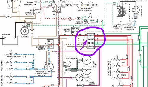
Diagrams of ignition wiring depict the wiring used to supply power to different parts of the vehicle. There are usually four colors-coded terminus of each part. Red is for accessories and yellow is for the battery, and green is the solenoid for starters. The “IGN” terminal is utilized to turn on the car, operate the wipers, as well as other features. The diagram below shows how to connect the ACC terminal and ST terminals to various components.
The battery is attached to the terminal named BAT. Without the battery the electrical system can not get started. In addition, the switch doesn’t turn on. It is possible to refer to your wiring diagram if you’re not sure where the batteries of your car are. The accessory terminals in your car are connected to the ignition switch and the battery. The BAT terminal connects to the battery.
Certain ignition switches have an independent “accessory” location, which allows users can manage their outputs without the ignition. Sometimes, customers may wish to utilize the auxiliary input independently of the ignition. To make use of the additional output, wire the connector in the same colors as ignition and connect it to the ACC terminal on the switch. While this is a convenient feature, there is one crucial distinction. Most ignition switches will be in an ACC position when the vehicle is in the ACC however they’ll be at the START position when the vehicle is in IGN.
Gallery of Mgb Ignition Switch Wiring Diagram
Gallery of Mgb Ignition Switch Wiring Diagram


