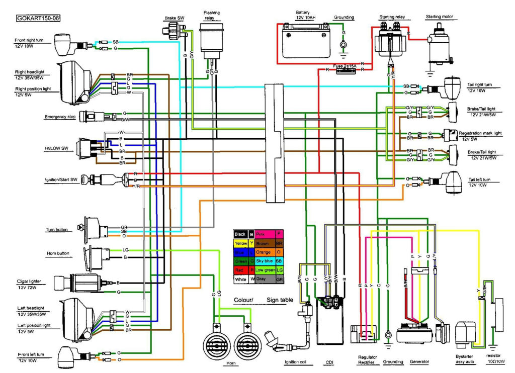
Moped Ignition Wiring Diagram – First, let’s take a look at the different types of terminals used on the ignition switch. These terminals comprise the Ignition switch and Coil and the Accessory. After we’ve identified the terminals used, we can begin to recognize the various parts of the Moped Ignition Wiring Diagram. We’ll also go over the roles of the Ignition switch and the Coil. After that, we will focus on the accessory terminals.
The terminals of the ignition switch
An ignition switch is made up of three switches. They are responsible for feeding the battery’s energy to various locations. The ON/OFF position of the ignition switch is controlled by the second switch, which provides power to the choke whenever it’s pulled. Different manufacturers utilize their own color-coding method for the different conductors, that is described in a separate article. OMC follows this system. This connector allows the attachment of a speedometer to the ignition switch.
While most ignition switch terminals are duplicated, the numbers might not match the diagram. To ensure that the wires are correctly connected to the ignition switch, you should check their continuity. A multimeter is an excellent tool to test the continuity. After you have verified the integrity of the wires you can install the connector. If you’re using a factory-supplied ignition switch, the wiring loom is different from the one in your car.
First, understand the differences between ACC and the auxiliary outputs. The ACC terminals as well as the IGN terminals serve as the default connections to the ignition switch. The START and IGN connections are the most important connections for radio and stereo. The ignition switch is the one that turns the car’s engine to and off. Older cars are identified by the alphabets “ACC”, “ST”, (for individual magneto cables) on their ignition switch terminals.
Terminals for coil
Understanding the terms is the initial step towards knowing what type of ignition coil you own. An ignition wiring diagram will show a variety of terminals and connections, comprising two primary and two secondaries. The coils have a specific operating voltage, and the first step in determining which type you have will involve testing the voltage of S1 the main terminal. S1 should also be tested for resistance to determine whether it’s a Type B, B, or A coil.
The low-tension coil side must be connected at the chassis’ minus. This is also the ground in the wiring diagram for ignition. The high tension part supplies positive directly the spark plugs. To prevent noise, the coil’s body metal must be connected to the chassis. It is not required to use electricity. The wiring diagram for the ignition will explain how to connect the terminals of either the positive or negative coils. It is possible to find an ignition coil problem that is easily identified by looking it up at an auto parts store.
The black-and-white-striped wire from the harness goes to the negative terminal. Positive terminal receives a white wire that includes a black trace. The black wire is connected to the contact breaker. To verify the connection, make use of a paperclip or pencil to lift them out of the plug housing. Also, make sure to check that the terminals haven’t been bent.
Accessory terminals
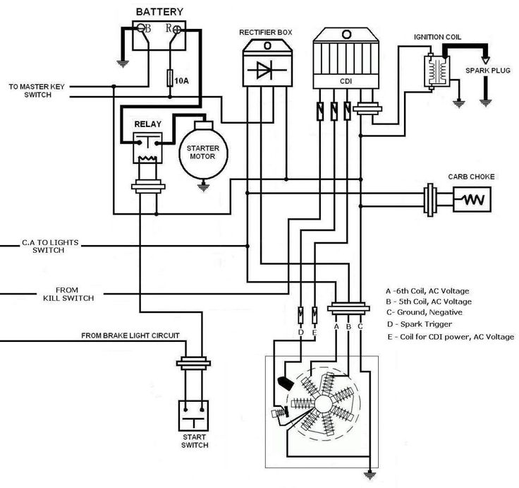
The ignition wiring diagrams illustrate the different wires used to power the various components of the vehicle. Typically, there are four different color-coded terminals for each component. Red refers to accessories, yellow is the battery and green is the starter solenoid. The “IGN terminal allows you to start the car, manage the wipers, or any other features that operate. The following diagram shows how to connect the ACC terminal and ST terminals to the other components.
The terminal called BAT is the location where the battery is. The electrical system can’t be started without the battery. In addition, the switch doesn’t turn on. You may refer to the wiring diagram if you’re uncertain about where the car’s batteries are. The ignition switch and battery are connected through the accessory terminals. The BAT terminal is connected to the battery.
Certain ignition switches come with an accessory position where users can alter their outputs as well as control them without the need to use the ignition. Some customers may prefer to utilize the auxiliary output separately from the ignition. It is possible to use the additional input by connecting the connector to the ACC terminal. This feature of convenience is fantastic however, there’s one difference. Many ignition switches have the ACC position when your vehicle is in the ACC mode, and a START position when it is in IGN.
Gallery of Moped Ignition Wiring Diagram
Gallery of Moped Ignition Wiring Diagram


