3.0 Mercruiser Ignition Coil Wiring Diagram – We will first examine the different types of terminals for the ignition switch. These terminals include the Ignition switch as well as the Coil as well as the Accessory. Once we know the purpose of these terminals and what they do, we can then identify the different parts in the ignition wiring. We will also cover the different functions of the Ignition Switch and Coil. Next, we’ll discuss the functions of the ignition switch and Coil.
The terminals of the ignition switch
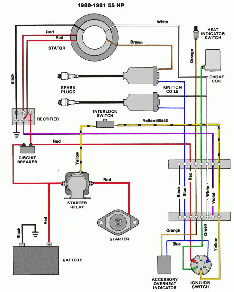
Three switches can be found on the ignition switch. Each of the three switches is able to feed the battery’s voltage to several different places. The first one is utilized to power the choke through pushing it. Then, the third switch is used to control the ON/OFF setting. Different manufacturers have distinct color-coding systems that correspond to the conductors. OMC utilizes the same system. A tachometer adapter is installed on the ignition switch, allowing for the addition of a tonometer.
Even though most ignition switch terminals don’t have an original number, they may have a different one. To make sure that your wires are correctly connected to the switch you should check their continuity. This can be done using an inexpensive multimeter. After you’re sure that all wires are in good order and you are able to connect the new connector. The wiring loom for an ignition switch that is supplied by the factory will be different from the one you have in your vehicle.
It is essential to know the way that ACC outputs and auxiliary outputs work in order to join them. The ACC, IGN and START terminals are the default connection to the ignition switch. They also function as the primary connections to the radio and stereo. The ignition switch regulates the engine in your car. On older cars the terminals of the ignition switch are identified with the initials “ACC” as well as “ST” (for distinct magnet wires).
Terminals for coil
Understanding the terms is the first step towards knowing what type of ignition coil you have. You will see several connections and terminals within the basic wiring diagram for ignition that include two primary as well as two secondary. The operating voltage of each coil differs. Therefore, it is crucial to test the voltage at S1 (primary terminal). To determine if the coil is an A, C, or B coil, it is recommended to also test S1’s resistance.
The negative end of the chassis should be connected to connect to the coil’s lower-tension end. This is the ground of the wiring for ignition. The high tension side supplies positive power directly to the spark plugs. The metal body of the coil needs to be connected to the chassis for suppression purposes however it isn’t electrically essential. The wiring diagram for ignition will also outline the connections of the positive coil terminals. Sometimes, a check at an auto parts store could detect a defective ignition wire.
The black-and-white-striped wire from the harness goes to the negative terminal. The positive terminal is connected to the white wire, which has the black trace. The black wire connects to the contact breaker. To verify the connections between the two wires use a paperclip to remove them from the housing. Make sure that the terminals aren’t bent.
Accessory terminals
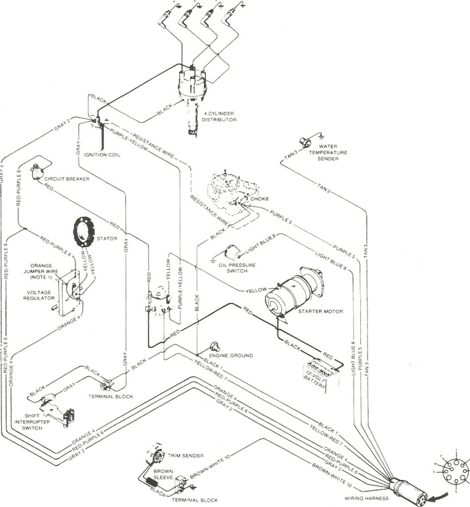
Ignition wiring diagrams show the various wires used to power the car’s various components. There are usually four different colors of terminals connected to each part. Red refers to accessories, yellow is the battery, and green the starter solenoid. The “IGN” terminal lets you start the car, manage the wipers or other functions. The diagram shows how to connect ACC or ST terminals as well as the rest.
The terminal BAT is where the battery is. The electrical system will not start without the battery. The switch won’t turn on if the battery isn’t present. If you’re not sure where your car’s battery is located, you can review your wiring diagram to see where it is. The ignition switch as well as the battery are connected via accessory terminals. The BAT terminal is connected to the battery.
Some ignition switches offer the option of an “accessory position” that lets users alter their outputs without the ignition. Some customers may prefer to use the auxiliary output independently of the ignition. Use the additional output by connecting it to an ACC terminal on the switch using the same colors. This option is useful however, it does have one major differentiator. Most ignition switches will have an ACC position when the vehicle is in ACC, but they will be at the START position if the car is in IGN.
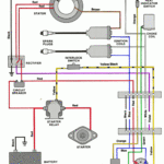
Gallery of 3.0 Mercruiser Ignition Coil Wiring Diagram
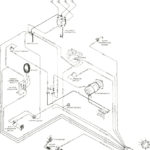
Gallery of 3.0 Mercruiser Ignition Coil Wiring Diagram


