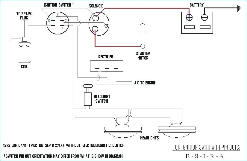
Mower Ignition Switch Wiring Diagram – We will first examine the different types of terminals for the ignition switch. They include terminals for the Ignition switch, Coil, and Accessory. Once we’ve determined the function of the terminals it is possible to recognize the various parts of the ignition wiring. Then, we will discuss the functions and the Coil. Following that, we’ll shift our attention to Accessory terminals.
Terminals of ignition switch
There are three separate switches on the ignition switch, and they provide the battery’s voltage to a variety of locations. The first switch is utilized to power the choke through pushing it. Then, another switch controls the ON/OFF position. Different manufacturers have different color-coding systems to identify different conductors. We’ll discuss this in a different article. OMC follows this system. Connectors can be attached to the ignition switch to connect the digital Tachometer.
While many ignition switch terminals don’t appear in their original configuration The numbering might not be in line with the diagram. Examine the integrity of the wires first to ensure they are correctly plugged in the ignition switch. A multimeter that is inexpensive can aid in this. Once you’re satisfied with the continuity it’s time to connect the new connector. If your vehicle is equipped with an ignition switch installed, the wiring diagram will differ.
It is important to know the differences between ACC and the auxiliary outputs. The ACC and IGN connectors are the default connections of your ignition switch. While the START, IGN, and ACC terminals are primary connections for radios or stereo, the START/IGN terminals are the primary ones. The ignition switch turns the car’s engine ON and OFF. The terminals of older vehicles’ ignition switches are labeled with “ACC” and ST (for the individual magneto wires).
Terminals for coil
Understanding the terms utilized is the initial step towards finding out the right kind of ignition coil to choose. A basic ignition wiring diagram will show a variety of connections and terminals, comprising two primary and two secondary. The coils have a specific operating voltage, and the first step in determining which type you have will involve testing the voltage at S1, the primary terminal. It is also recommended to test S1 for resistance to identify if it’s an A, B, or C coil.
The coil’s low-tension component must be connected with the chassis’ positive. This is the wiring diagram you will see in the wiring diagram. The high-tension side delivers positively directly to the spark plugs. For suppression purposes the body of the coil must be connected to chassis. It is not necessary to connect the coil electrically. The wiring diagram of the ignition will explain how to connect the terminals of the positive and negative coils. Sometimes, an inspection at an auto part store can identify a problem with the ignition wire.
The black-and-white-striped wire from the harness goes to the negative terminal. The terminal that is negative is served by the black trace that’s connected to the white wire. The black wire connects with the contact breaker. To verify the connection, make use of a paperclip or pencil to remove them of the plug housing. It’s also essential to make sure the terminals don’t bend.
Accessory terminals
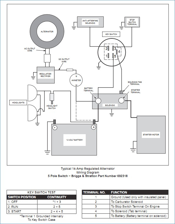
The diagrams for ignition wiring illustrate the wires used in the vehicle’s power supply. There are generally four colored terminals that correspond to the respective component. Accessories are red, the battery is yellow, the starter solenoid is green. The “IGN” terminal allows you to start your car, operate the wipers, and any other functions. The diagram shows the connection to the ACC- and ST terminals.
The battery is attached to the terminal whose name is BAT. The electrical system can’t start without the battery. Furthermore, the switch won’t begin to turn on. A wiring diagram can show you where to find your car’s battery. The accessory terminals of your car are connected to the battery as well as the ignition switch. The BAT terminal is connected to the battery.
Certain ignition switches provide an additional “accessory position” which allows users to adjust their outputs independently of the ignition. Some customers prefer to utilize an additional output that is not connected to the ignition. Use the additional output by connecting the connector to the ACC terminal on the switch with the same colors. This feature is convenient however, it does have one key distinction. Most ignition switches are designed to have an ACC status when the vehicle is at either the ACC or START positions.
Gallery of Mower Ignition Switch Wiring Diagram
Gallery of Mower Ignition Switch Wiring Diagram


