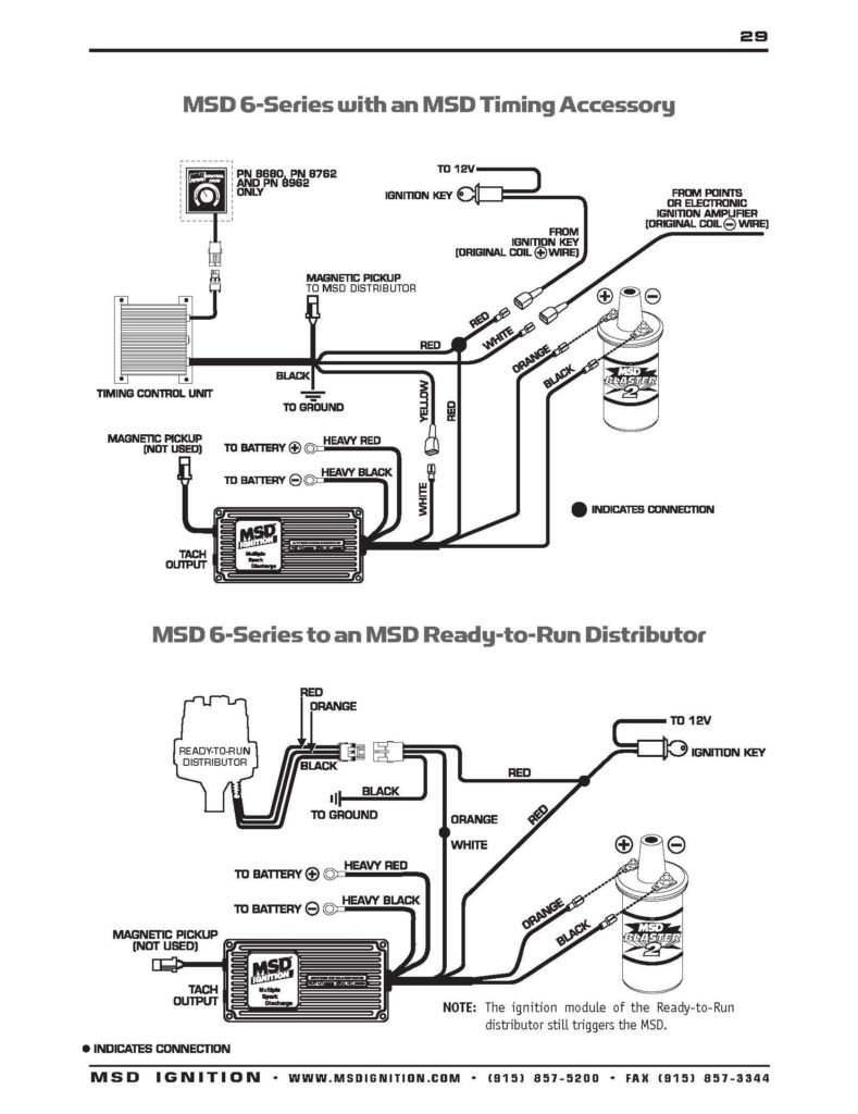
Msd Ignition 6a Wiring Diagram – We will first look at the various types and purposes of the terminals on the ignition switches. These terminals are for the Ignition button, Coil and Accessory. Once we have identified the purpose of these terminals, we will identify the different parts in the ignition wiring. We will also talk about the functions as well as the Coil. Then, we’ll talk about the function of the ignition switch and Coil.
The terminals are for ignition switches.
The ignition switch has three switches. They feed the voltage of the battery to different places. The ON/OFF setting of the switch that controls the ignition is managed by the first switch, which supplies power to the choke when it is pushed. Different manufacturers employ different color codes for various conductors. This is discussed in a different article. OMC uses this system. A connector is also included inside the ignition switch for connecting an Tachometer.
While most ignition switch terminals are duplicated, the numbers might not be in line with the diagram. Before plugging into the ignition switch, make sure to check the continuity. A multimeter that is inexpensive can aid in this. When you’re happy with the connection then you can connect the new connector. The wiring loom used in an ignition system switch that is supplied by the manufacturer differs.
Before you can connect the ACC outputs to your car’s auxiliary outputs it is crucial to understand the basics of these connections. The ACC terminals as well as the IGN terminals are the standard connections for the ignition switch. The START and IGN connections are the most important connections for stereo and radio. The ignition switch turns the engine of your car ON and off. The ignition switch terminals on older cars are labeled with the letters “ACC” and “ST” (for the individual magneto wires).
Terminals for coil
To determine the type of ignition coil, the initial step is to learn the definition of. You’ll see a number of connections and terminals within an ignition wiring schematic that include two primary as well as two secondary. The coils are equipped with a particular operating voltage, and the first method of determining what type you’re using is to test the voltage at S1, the primary terminal. To determine if the coil is a Type A, C or B coil you should also test S1’s resistance.
The chassis’ negative end should be connected to connect the coil’s low-tension end. This is the wiring diagram you will see on the diagram of wiring. The high-tension component supplies the spark plugs with positive. To reduce the noise the coil’s metal body must be connected with the chassis. It’s not necessary to use electricity. A wiring diagram can show the connection between the positive and negative coils. It is possible to find an issue with the ignition coil which can be identified by scanning it in an auto parts store.
The black-and-white-striped wire from the harness goes to the negative terminal. The other white wire has a black trace on it, and connects to the positive terminal. The black wire connects with the contact breaker. To test the connections between the two wires employ a paperclip to lift them off the housing. Also, make sure that the connections aren’t bent.
Accessory terminals
The ignition wiring diagrams illustrate the different wires that are used to power various components of the vehicle. There are generally four color-coded terminus for each component. To identify accessories, red stands the starter solenoid’s color, blue for battery, and blue for accessory. The “IGN” terminal is utilized to turn on the car, operate the wipers, and other features. This diagram shows how you can connect ACC and ST terminals with the other components.
The terminal BAT is the connection for the battery. The battery is vital for the electrical system to begin. Additionally, the switch doesn’t turn on. You can refer to your wiring diagram if you’re uncertain about where the car’s batteries are located. The accessory terminals on your car connect to the battery as well as the ignition switch. The BAT connector is connected to the battery.
Some ignition switches are equipped with an additional position. This allows users to access their outputs from another location without the ignition. Sometimes, a customer wants to make use of an auxiliary output that is separate from the ignition. Make use of the auxiliary output by connecting it to the ACC terminal on the switch that has the same color. This is an excellent option, but there’s an important difference. Most ignition switches will be in an ACC position if the car is in the ACC however, they will be at the START position when the vehicle is IGN.
Gallery of Msd Ignition 6a Wiring Diagram
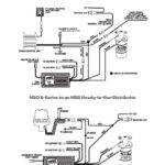
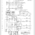
Gallery of Msd Ignition 6a Wiring Diagram


