Rotax Ducati Ignition Wiring Diagram – In the beginning, we’ll examine the various types of terminals that are found in the ignition switch. These terminals serve for the Ignition button, Coil and Accessory. Once we understand the function of each terminal, we are able to determine the components of the ignition wiring. We will also cover the functions of both the Ignition Switch and the Coil. After that, we will turn our attention towards the accessories terminals.
Terminals for ignition switch
An ignition switch contains three different switches that direct the battery’s current to various destinations. The first one is utilized to turn on the choke through pushing it. Then, the second is for the ON/OFF setting. Different manufacturers have different colors for various conductors. This is explained in another article. OMC uses this method. The connector allows for the attachment of a speedometer the ignition switch.
While the majority of ignition switch terminals don’t have an original number, they may have a different number. The first step is to check the continuity of all the wires to ensure they are correctly connected to the ignition switches. You can do this with an inexpensive multimeter. After you’re satisfied with the connection, you can place the new connector. The wiring loom used for the ignition switch factory-supplied will be different than the one you have in your car.
To connect the ACC outputs to the auxiliary outputs on your vehicle, you have to understand how these two connections work. The ACC, IGN and START terminals are your default connection to the ignition switch. They also function as the primary connections to your radio and stereo. The ignition switch is responsible for turning the car’s engine on and off. The terminals on older cars’ ignition switches are labeled with “ACC” and ST (for the individual magneto wires).
Coil terminals
Understanding the terminology is the first step to finding out what kind of ignition coil you own. A basic ignition wiring layout will reveal a variety of connections and terminals. You must determine the type of coil that you own by examining the voltage on the primary terminal, called S1. To determine whether it’s an A, C or B coil, it is recommended to also test S1’s resistance.
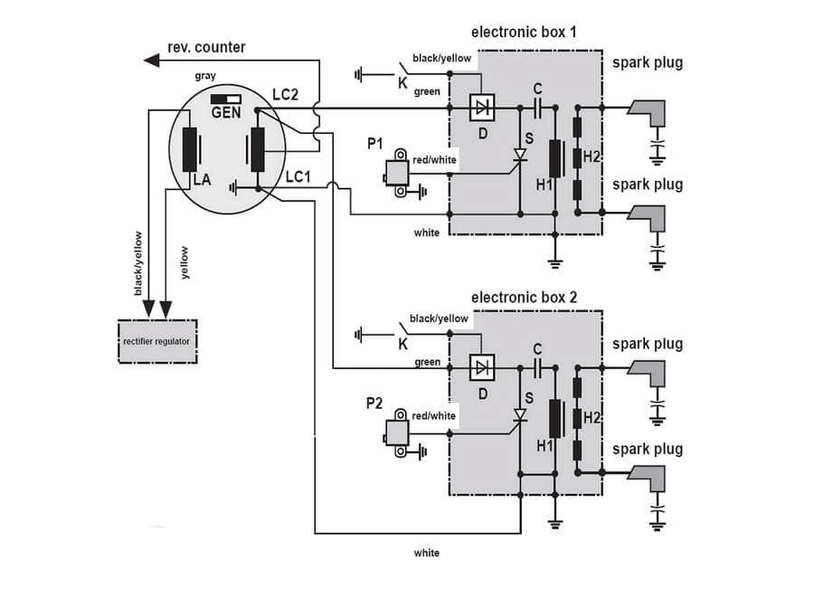
The coil’s low-tension side should be connected at the chassis’s plus. This is also the ground in the ignition wiring diagram. The high-tension side connects the spark plugs to a positive. The metal body of the coil needs to be connected to the chassis for suppression purposes but is not electrically essential. A wiring diagram can also depict the connection between positive and negative coil terminals. It is possible to find an issue with your ignition coil which can be identified by scanning it in an auto parts store.
The black-and-white-striped wire from the harness goes to the negative terminal. The positive terminal is connected to the white wire and an trace in black. The black wire connects with the contact breaker. To verify the connections between the two wires use a paperclip to remove them from the housing. Be sure that the terminals aren’t bent.
Accessory Terminals
Ignition wiring diagrams depict the various wires utilized for powering the different components. In general, there are four different colored terminals for each part. The red color represents accessories, yellow for the battery and green for the solenoid for starters. The “IGN terminal lets you start your car, operate the wipers, or any other operation features. This diagram shows how to connect ACC and ST terminals with the rest of components.
The terminal BAT is the connector for the battery. The electrical system will not start if the battery isn’t connected. In addition, the switch doesn’t turn on. It is possible to refer to your wiring diagram if not sure where the batteries of your car are located. The accessory terminals of your car are connected with the battery and ignition button. The BAT terminal is connected with the battery.
Some ignition switches come with an accessory position. This lets users connect their outputs to another location without the ignition. Some customers may prefer to use the auxiliary output separately from the ignition. You can use the secondary output by connecting it to the ACC terminal on your switch with the same colors. This feature of convenience is fantastic however, there’s one difference. Many ignition switches have the ACC position when your car is in ACC mode and a START position when the switch is in IGN.
Gallery of Rotax Ducati Ignition Wiring Diagram
Gallery of Rotax Ducati Ignition Wiring Diagram


