Mtd Ignition Switch Wiring Diagram – First, we will take a look at the various kinds of terminals that are found in the ignition switch. These are terminals for the Ignition, Coil, or Accessory. Once we know the purpose of each terminal, we are able to identify the various components of the ignition wiring. We’ll also discuss the roles of the Ignition switch, and Coil. Then we’ll proceed to the Accessory Terminals.
The ignition switch’s terminals
An ignition switch is made up of three switches. They are responsible for feeding the battery’s power to several destinations. The ON/OFF position of the switch that controls the ignition is managed by the second switch, which supplies power to the choke whenever it’s pulled. Different manufacturers employ different colors for different conductors. This is explained in another article. OMC utilizes this method. Connectors can be attached to the ignition switch in order to add an electronic Tachometer.
Although the majority of ignition switch terminals do not appear in their original configuration, the numbering may not match the diagram. Before you plug into the ignition switch, be sure to test the continuity. A multimeter that is inexpensive can aid in this. Once you’re satisfied with the continuity, you can place the new connector. If you’re using an ignition switch supplied by the manufacturer the wiring loom may be different from that in your car.
In order to connect the ACC outputs to the auxiliary outputs of your car, you need first know the way these two connections function. The ACC/IGN terminals act as the default connections for the ignition switch. The START/IGN terminals connect to the radio or stereo. The ignition switch is the one that controls the engine of your car. Older vehicles have ignition switch terminals marked “ACC” or “ST” (for individual magnetowires).
Terminals for coil
Understanding the terms is the initial step towards knowing what type of ignition coil you have. An ignition wiring diagram will display a range of connections and terminals, which include two primary terminals and two secondary. The coils come with a distinct operating voltage. The initial step to determine which one you have will involve testing the voltage at S1, the primary terminal. S1 must also go through resistance tests to determine if it’s an A or B coil.
The coil’s low-tension component must be connected to the chassis’ positive. This is the ground in the diagram of the ignition wiring. The high-tension side is a positive connection to the sparkplugs. For suppression purposes the body of the coil must be connected to the chassis. It is not necessary to connect the coil electrically. The ignition wiring diagram will also reveal the connections between the negative and positive coil terminals. Sometimes, a check at an auto parts shop can diagnose a malfunctioning ignition wire.
The black-and-white-striped wire from the harness goes to the negative terminal. The positive terminal also receives the second white wire, which is black in its trace. The black wire connects to the contact breaker. You can take the black wire from the plug housing with a paper clip if you are unsure about the connection. Make sure that the terminals do not bend.
Accessory terminals
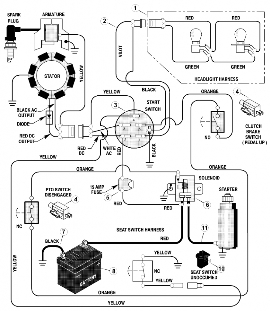
Diagrams of ignition wiring depict the wiring used to power various parts of the vehicle. There are usually four color-coded terminus for each component. Red is for accessories and yellow is for the battery, and green is the starter solenoid. The “IGN” terminal can be used to start the car, turn on the wipers, as well as other functions. The following diagram shows how to connect both the ACC terminal as well as the ST terminals to the other components.
The terminal BAT is the connection for the battery. The battery is necessary to allow the electrical system to get started. In addition the switch isn’t turned on. You can refer to your wiring diagram if you’re not sure where the batteries of your car are. Your car’s accessory terminals are connected to the ignition switch as well as the battery. The BAT Terminal is connected to the battery.
Some ignition switches feature an “accessory” position that allows users to control their outputs , without needing to turn on the ignition. Sometimes, customers wish to make use of the auxiliary output separate from the ignition. To use the auxiliary output, connect the connector with the same colors as the ignition and connect it to the ACC terminal on the switch. Although this is a useful feature, there’s one important difference. Most ignition switches come with the ACC position when your vehicle is in the ACC mode and a START position when you are in IGN.
Gallery of Mtd Ignition Switch Wiring Diagram
Gallery of Mtd Ignition Switch Wiring Diagram


