Outboard Ignition Wiring Diagram – The first step is to examine the different types of terminals on the ignition switch. They include terminals for the Ignition switch, Coil, and Accessory. Once we’ve determined the function of these terminals, it is possible to recognize the various parts of the ignition wiring. We will also discuss the function of the Ignition switch and Coil. We will then concentrate on the accessory terminals.
The terminals are for ignition switches.
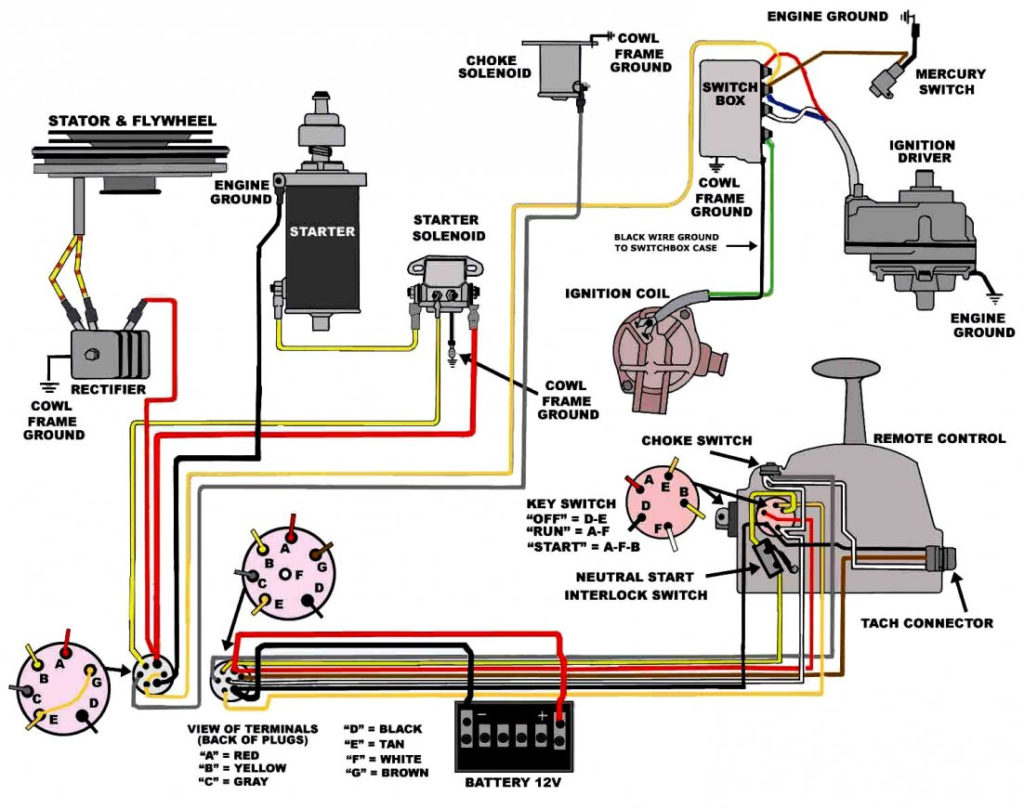
An ignition switch contains three separate switches that feed the battery’s current to different destinations. The ON/OFF state of the switch that controls the ignition is managed by the second switch, which delivers power to the choke whenever it’s pushed. Different manufacturers employ different color codes for various conductors. This is described in another article. OMC follows this approach. The connector permits the attachment of a speedometer to the ignition switch.
While many ignition switch terminals don’t come in original form, the numbering may not be in line with the diagram. Verify the integrity of the wires first to ensure they’re properly connected to the ignition switch. This can be checked with a simple multimeter. Once you are satisfied with the continuity of the wires, install the new connector. If your car has an ignition switch that is installed, the wiring diagram will differ.
You must first understand the ways in which the ACC outputs and the auxiliary outputs work in order to connect them. The ACC/IGN connections function as the default connection on the ignition switch. The START/IGN terminals connect to the radio or stereo. The ignition switch acts as the engine’s switch to turn off or on. The terminals for the ignition switch on older vehicles are marked with the alphabets “ACC” and “ST” (for the individual magneto wires).
Coil terminals
Understanding the terms that is used is the initial step towards determining what kind of ignition coil to choose. In a basic ignition wiring diagram you’ll see several different terminals and connections, including two primary and two secondary. Each coil operates at a specific voltage. The first step to determine which kind of coil you’re using is to examine the voltage of S1 or the primary terminal. S1 should also be checked for resistance in order to identify whether it’s a Type B, B or A coil.
The coil with low tension must be connected at the chassis’ minus. It is also the ground for an ignition wiring diagram. The high-tension end supplies positive direct to the sparkplugs. The aluminum body of the coil needs to be linked to the chassis for suppression but isn’t required. The ignition wiring diagram will also show how to connect the positive coil terminals. In some instances, you’ll find that a malfunctioned ignition coil can be diagnosed with scans at an auto parts shop.
The black-and-white-striped wire from the harness goes to the negative terminal. The positive terminal receives the other white wire and the black trace. The black wire is connected to the contact breaker. To test the wires’ connections, employ a paperclip to remove them from the housing. Also, ensure that the terminals aren’t bent.
Accessory Terminals
The ignition wiring diagrams illustrate the different wires that are used to power the car’s various parts. Typically there are four color-coded terminals for each component. Red is for accessories and yellow is for the battery, and green is for the starter solenoid. The “IGN” terminal can be used to start the car , and also to operate the wipers as well as other operational features. The diagram illustrates the connection between the ACCand ST terminals.
The terminal BAT connects the battery to the charger. The electrical system won’t start without the battery. The switch also won’t start without the battery. It is possible to refer to your wiring diagram if you’re unsure where your car’s batteries are. The accessory terminals of your vehicle are connected to the battery as well as the ignition button. The BAT Terminal is connected to the battery.
Certain ignition switches come with an additional position in which users can modify their outputs as well as control them without needing to use the ignition. Customers sometimes want the auxiliary output to be used separately from the ignition. It is possible to use the auxiliary input by connecting it to the ACC terminal. Although this is a useful feature, there’s one significant difference. Most ignition switches will be in an ACC position when the vehicle is in ACC, but they will be in the START position if the vehicle is IGN.
Gallery of Outboard Ignition Wiring Diagram
Gallery of Outboard Ignition Wiring Diagram


