Murray Ignition Switch Wiring Diagram – Let’s first examine the different types and purposes of the terminals in the ignition switches. These include the terminals for the Ignition switch, Coil, and Accessory. Once we know the purpose of each terminal, we can then determine the components of the ignition wiring. We will also talk about the functions as well as the Coil. After that we will move on to the Accessory Terminals.
The terminals are for ignition switches.
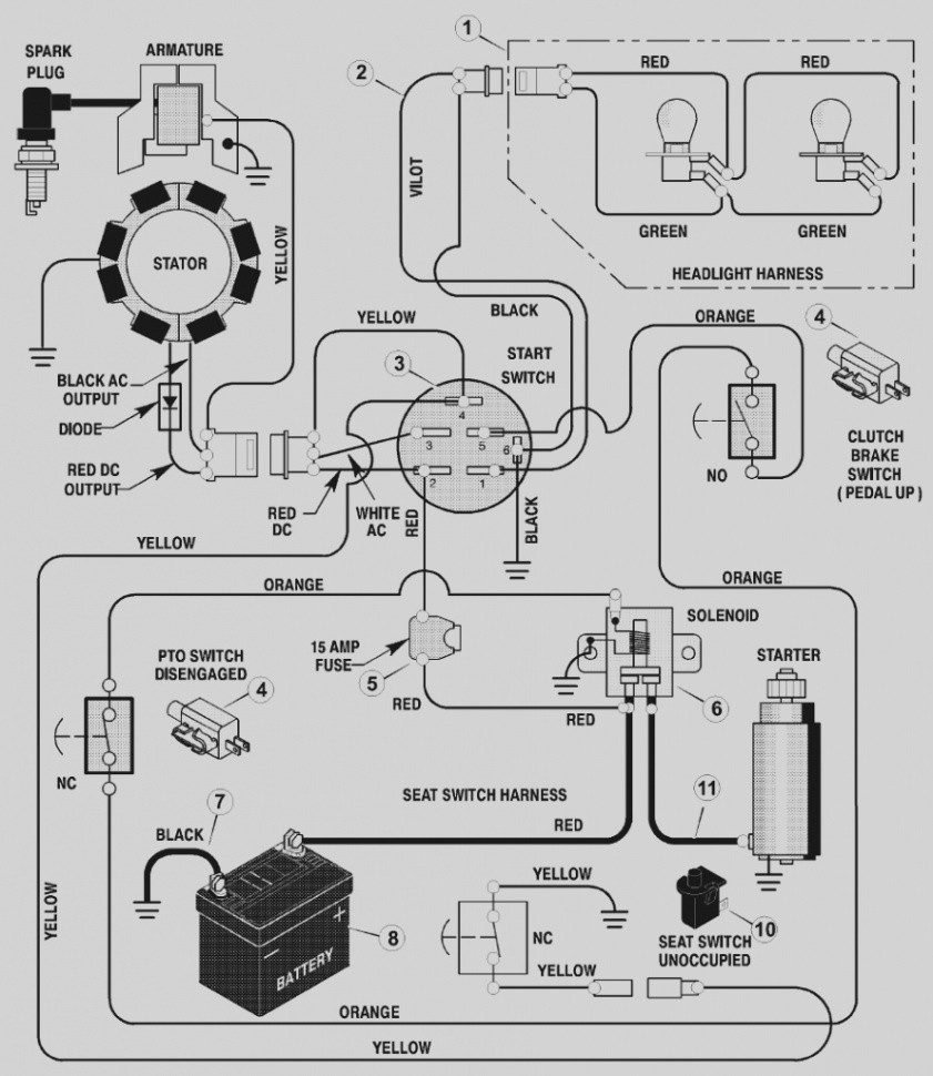
An ignition switch contains three separate switches that feed the battery’s power to various destinations. The first switch supplies power to the choke when it is pushed. The third is the position of the ignition switch’s ON/OFF. Different manufacturers use different colors-coding systems to match the conductors. OMC uses this approach. The ignition switch also includes a connector for adding an timer.
Even though some of the ignition switch terminals could not be original, the numbers of each one might not be in line with the diagram. Check the continuity of all wires to make sure they’re properly plugged into the ignition switches. You can check this using a simple multimeter. When you are satisfied with the continuity of the wires you can connect the new connector. If your vehicle has an original ignition switch supplied by the factory (or a wiring loom) The wiring loom will differ from that of the car.
The first step is to understand the distinctions between ACC and secondary outputs. The ACC, IGN and START terminals are the default connections to the ignition switch. They are also the main connections to the radio and stereo. The ignition switch switches the car’s engine ON and OFF. Older vehicles have ignition switch terminals labeled “ACC” or “ST” (for individual magnetowires).
Terminals for coil
The terms used to define the kind and model of an ignition coil is the primary thing. An understanding of the basic wiring diagram for ignition will provide you with a range of terminals and connections. Each coil has a specific operating voltage. To determine the type of coil you have the first step is to check the voltage at S1, which is the primary terminal. S1 must also be subjected to resistance testing to determine if it is an A or B coil.
The negative end of the chassis end should be connected to to the coil’s lower-tension end. This is what you see in the diagram of wiring. The high-tension supply supplies positive directly to spark plugs. The body of the coil has to be connected to the chassis to prevent it from being smothered however it isn’t electrically necessary. You will also see the connections of the positive and negative coil’s terminals on an ignition wiring diagram. In certain instances it is possible to find a malfunctioned ignition coil is identified by scans at an auto parts store.
The black-and-white-striped wire from the harness goes to the negative terminal. The other white wire is black-colored and goes to the negative terminal. The black wire connects to the contact breaker. If you’re unsure of the connections between the two, try using an old paper clip to take them from the housing of the plug. Be sure the terminals do not bend.
Accessory Terminals
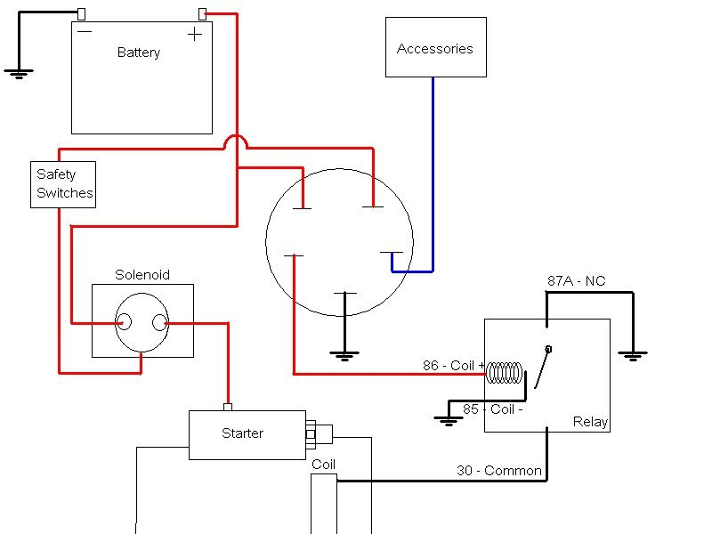
The ignition wiring diagrams show the various wires utilized to power the different components. In general there are four color-coded terminals for each component. The red symbol represents accessories, yellow represents the battery and green is for the starter solenoid. The “IGN” terminal can be used to start the vehicle and control the wipers as well as other operational features. The below diagram shows how to connect the ACC terminal as well as the ST terminals to the other components.
The terminal BAT holds the battery. Without the battery the electrical system will not begin. In addition, the switch will not begin to turn on. You may refer to the wiring diagram if unsure where your car’s batteries are. The ignition switch and the battery are connected through the accessory terminals. The BAT connector is connected to your battery.
Some ignition switches include an accessory position where users can adjust their outputs and control them without having to turn on the ignition. Customers may want to utilize the auxiliary output in addition to the ignition. In order for the auxiliary output be used, plug in the connector in the same shade as the ignition. Then connect it with the ACC end of the switch. This is a convenient feature however it does have one significant differentiator. The majority of ignition switches are set to be in an ACC position when the vehicle is in the ACC position, while they’re set to the START position when the vehicle is in the IGN position.
Gallery of Murray Ignition Switch Wiring Diagram
Gallery of Murray Ignition Switch Wiring Diagram


