Onan Ignition Coil Wiring Diagram – Let’s first examine the various terminals on the ignition switch. These are the terminals that connect the Ignition, Coil, or Accessory. Once we know the purpose of these terminals, we will be able to identify the various parts of the ignition wiring. We’ll also go over the roles of the Ignition switch and Coil. The next step is to focus to the accessory terminals.
Ignition switch terminals
An ignition switch contains three different switches that direct the battery’s current to different locations. The first one is utilized to drive the choke by pushing it. Then, the third switch is used to control the ON/OFF position. Different manufacturers use different color-coding methods for different conductors. This will be covered in a separate article. OMC follows this procedure. Connectors can be attached to the ignition switch in order to add an electronic tachometer.
While most ignition switch terminals are not original, the numbers for each one may not be in line with the diagram. Before plugging in the ignition switch, make sure to check the continuity. A cheap multimeter can help you do this. After you have verified that the wires are in good condition, you can install the connector. If your car is equipped with an original factory-supplied ignition switch (or an electrical loom) The wiring loom may differ from the one in your car.
Before connecting the ACC outputs to your car’s auxiliary outputs It is essential to be familiar with the fundamentals of these connections. The ACC and IGN connectors are the standard connections for your ignition switch. The START, IGN, and ACC terminals are the primary connections for the radio or stereo, the START/IGN connections are the primary ones. The ignition switch turns the engine of your car ON and off. The terminals for the ignition switch on older vehicles are marked with the letters “ACC” and “ST” (for the individual magneto wires).
Terminals for coil
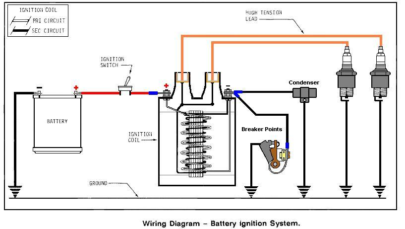
To figure out the type of ignition coil, the initial step is to know the terms. The basic ignition wiring diagram shows a number different connections and terminals. There are two primary and one secondary. It is essential to identify the type of coil you own by examining the voltage on the primary terminal S1. S1 must also be inspected for resistance to determine if it’s a Type B, B, or an A coil.
The low-tension coil side must be connected to the chassis’s plus. This is the ground in the wiring diagram for ignition. The high-tension side provides the spark plugs with positive. The metal body of the coil needs to be connected to the chassis to prevent it from being smothered however it isn’t electrically necessary. The wiring diagram of the ignition will explain how to connect the two terminals of the negative or positive coils. Sometimes, a visit to an auto part store can detect a defective ignition wire.
The black-and-white-striped wire from the harness goes to the negative terminal. The positive terminal also receives a second white wire, which is black in its trace. The black wire connects to the contact breaker. To check the connections between the two wires, employ a paperclip to lift them out of the housing. Also, make sure that the connections are not bent.
Accessory terminals
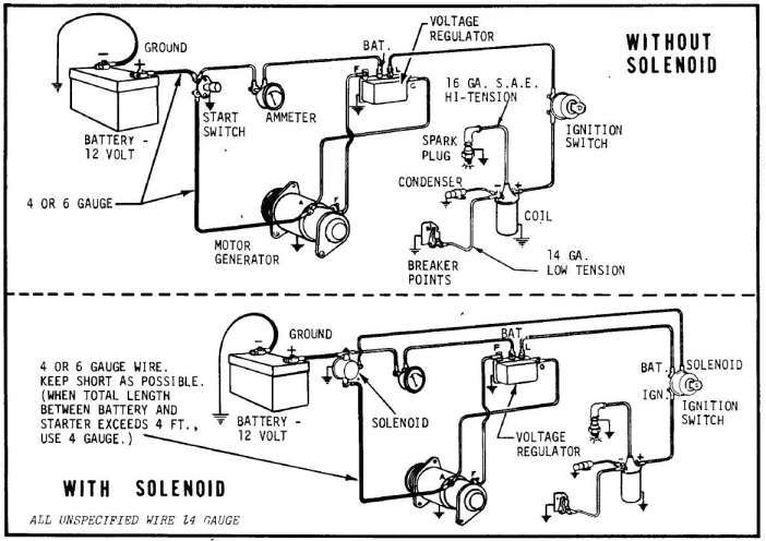
Diagrams of ignition wiring show the wiring used in the power supply of the vehicle. There are usually four color-coded terminus for each component. To identify accessories, red is for starter solenoid, yellow is for battery, and blue is for accessories. The “IGN terminal is used for starting the vehicle, controlling the wipers and other functions. The diagram shows how you can connect the ACC and ST terminals to the rest of the components.
The terminal BAT connects the battery to the charger. The electrical system can’t be started without the battery. The switch will not turn off if the battery isn’t present. It is possible to view your wiring diagram to determine where your car’s batteries are located. The accessory terminals in your vehicle connect to the battery as well as the ignition switch. The BAT Terminal is connected to the Battery.
Some ignition switches come with an additional position. This allows users to access their outputs from a different location without the ignition. Some customers may prefer to utilize the auxiliary output in addition to the ignition. Make use of the auxiliary output by connecting the connector to the ACC terminal on the switch that has the same color. This option is useful, but it has one significant differentiator. Most ignition switches are configured to show an ACC status when the vehicle is in either the ACC or START position.
Gallery of Onan Ignition Coil Wiring Diagram
Gallery of Onan Ignition Coil Wiring Diagram


