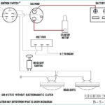
Murray Riding Lawn Mower Ignition Switch Wiring Diagram – We’ll begin by looking at the different types terminals found on the ignition switch. These terminals are for the Ignition button, Coil and Accessory. Once we have established the purpose of these terminals are used for, we will proceed to discover the various components of the Murray Riding Lawn Mower Ignition Switch Wiring Diagram. Then, we will discuss the functions and the Coil. The next step is to focus to the accessory terminals.
The ignition switch’s terminals
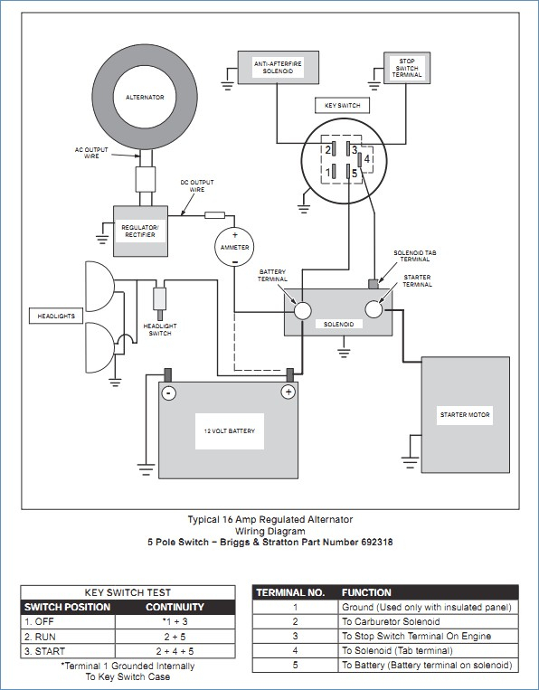
The ignition switch consists of three different switches. These are the ones that supply the battery’s power to several locations. The first switch is used to turn on the choke by pushing it. Then, the second is for the ON/OFF setting. Different manufacturers have different color-coding systems that correspond to the conductors. OMC utilizes this approach. The adapter is attached to the ignition switch to allow the installation of the tachometer.
Even though some of the ignition switch terminals might not be original, the numbering of the terminals may not be in line with the diagram. To ensure that your wires are connected to the switch you must verify their continuity. This can be checked using a simple multimeter. Once you’re satisfied with the quality of the connection it’s time to connect the new connector. If your vehicle has an original factory-supplied ignition switch (or an electrical loom), the wiring loom might differ from the one in your vehicle.
Before you can connect the ACC outputs to the auxiliary outputs of your car It is essential to be familiar with the fundamentals of these connections. The ACC and IGN terminals are the default connection on your ignition switch. the START and IGN terminals are the main connections for the stereo and radio. The ignition switch is responsible for turning the car’s engine on and off. The terminals of the ignition switch on older cars are identified with the letters “ACC” as well as “ST” (for the individual magneto wires).
Terminals for Coil
The first step in determining the type of ignition coil is to understand the terms that is used. In a typical diagram of the wiring for ignition you’ll see various connections and terminals, which include two primary and two secondary. Each coil is equipped with a distinct operating voltage. To determine the type of coil you’ve got, the first step is to check the voltage at the S1 primary terminal. To determine if the coil is a Type A, C or B coil, you should also test S1’s resistance.
The chassis’ negative needs to be connected to the side of low-tension. This is the wiring diagram you will see on the diagram of wiring. The high-tension supply provides positive directly to spark plugs. To prevent noise the body of the coil must be connected to the chassis. However, it is not required to connect electrically. A wiring diagram can show the connection between the positive and negative coil terminals. Sometimes, a visit to an auto part store can detect a defective ignition wire.
The black-and-white-striped wire from the harness goes to the negative terminal. The positive terminal receives the other white wire with the trace of black. The contact breaker is attached to the black wire. If you’re not certain about the connections of the two, try using a paper clip to remove them from the housing of the plug. It’s also essential to make sure that the terminals don’t bend.
Accessory terminals
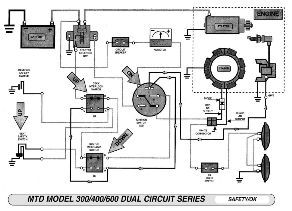
The diagrams for ignition wiring show the wires used in the vehicle’s power supply. Each component has four distinct color-coded connections. Accessories are red and the battery yellow and the starter solenoid green. The “IGN” terminal is used to start the car, operating the wipers and other functions. The following diagram illustrates how to connect the ACC terminal and ST terminals to various components.
The terminal BAT is where the battery is. Without the battery the electrical system will not start. A dead battery could make the switch stop turning on. It is possible to refer to your wiring diagram if not sure where the batteries of your car are located. The ignition switch and the battery are connected by the accessory terminals. The BAT Terminal is connected to the battery.
Certain ignition switches come with an accessory setting where users can alter their outputs and control them without having to turn on the ignition. Some customers prefer to utilize an additional output independent of the ignition. The auxiliary output can be utilized to connect the connector with the same color as your ignition and attaching it to the ACC terminal of the switch. Although this is a great feature, there’s one thing to be aware of. Most ignition switches are configured to be in an ACC position when the car is in the ACC position, but they’re set to the START position when the car is in the IGN position.
Gallery of Murray Riding Lawn Mower Ignition Switch Wiring Diagram
Gallery of Murray Riding Lawn Mower Ignition Switch Wiring Diagram


