Omc Push To Choke Ignition Switch Wiring Diagram – The first step is to look at the various types of terminals for the ignition switch. They include terminals for Coil, Ignition Switch, and Accessory. After we’ve identified the purpose of these terminals, we can recognize the various parts of the ignition wiring. We’ll also be discussing the roles of the Ignition switch and Coil. After that, we’ll turn our attention to Accessory terminals.
Terminals for ignition switches
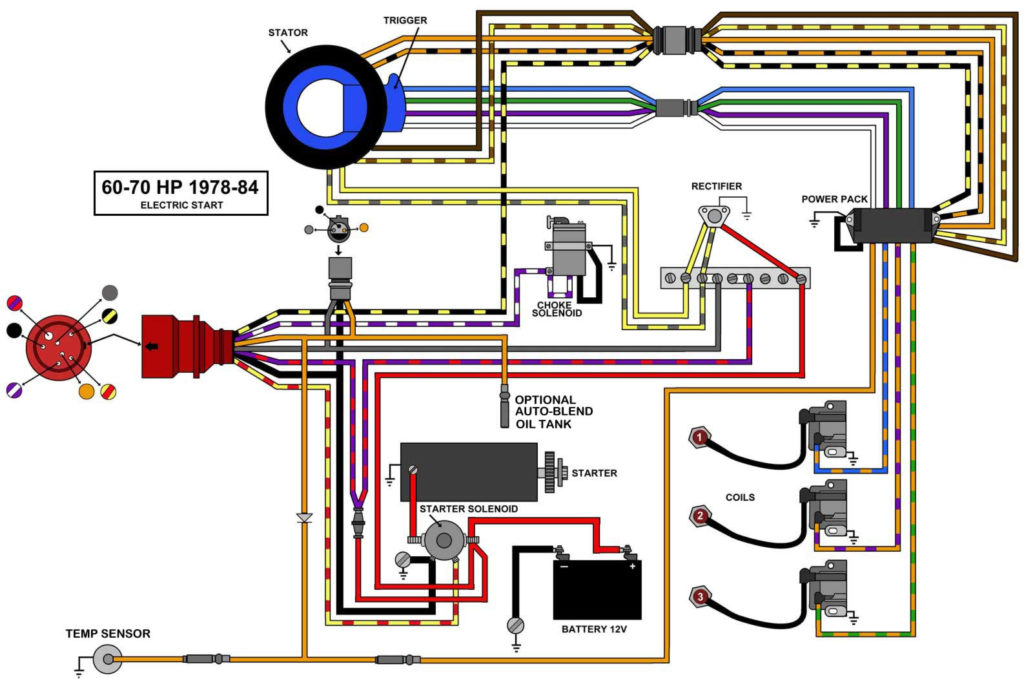
An ignition switch is comprised of three switches. They supply the voltage of the battery to many different locations. The first switch is the one that supplies the choke with power, and the third switch toggles the state of the switch. Different manufacturers have distinct colour-coding systems that correspond to the conductors. OMC utilizes the same system. A tachometer adapter is installed on the ignition switch that allows for the addition of a tonometer.
Although the majority of ignition switch terminals are not original, the numbers for each may not match the diagram. First, check the continuity of all wires to ensure that they are properly connected to the ignition switches. This can be done with a simple multimeter. When you’re happy with the connection then you can connect the new connector. The wiring loom used in a factory-supplied ignition system switch is different.
You must first understand how the ACC outputs and auxiliary outputs function in order to join them. The ACC and IGN connectors are the standard connections of the ignition switch. Although the START, IGN, and ACC terminals are the primary connections to the radio or stereo, the START/IGN terminals are the most important ones. The ignition switch is responsible to turn the car’s engines on and off. Older cars are identified by the alphabets “ACC”, “ST”, (for individual magneto cables) at their ignition switch’s terminals.
Terminals for coil
Understanding the terms is the initial step towards determining which type of ignition coil you’ve got. You’ll see a number of connections and terminals on an ignition wiring schematic that include two primary as well as two secondary. Each coil has an operating voltage. The first step in determining which kind of coil you’re dealing with is to test the voltage on S1, or the primary terminal. S1 should also be tested for resistance to determine if it’s an A, Type B or an A coil.
The negative of the chassis must be connected to the low-tension side. It is also the ground on an ignition wiring diagram. The high-tension component supplies the positive power direct to the spark plugs. The body of the coil has to connect to the chassis to prevent it from being smothered, but it is not electrically essential. The diagram of the ignition wiring will also show you the connection of the negative and positive coil’s terminals. In certain instances you’ll discover that the ignition coil is damaged and can be diagnosed with a scan at an auto parts shop.
The black-and-white-striped wire from the harness goes to the negative terminal. The terminal for the negative is served by the black trace attached to the white wire. The black wire is connected to the contactbreaker. To test the connections between the two wires use a paperclip to remove them off the housing. Be sure to ensure that the terminals have not been bent.
Accessory terminals
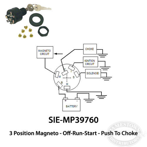
Diagrams of ignition wiring depict the wiring used to power the vehicle’s electrical supply. There are typically four different color-coded terminus for each component. To identify accessories, red stands for starter solenoid, blue for battery, and blue for accessory. The “IGN” terminal is used to start the car , and also to operate the wipers and other operating functions. The diagram shows how to connect ACC or ST terminals and the rest.
The terminal referred to as BAT is the place where the battery is. The battery is essential for the electrical system to begin. Furthermore, the switch won’t begin to turn on. To find the battery in your car, check your wiring diagram. The ignition switch is connected to the car’s battery. The BAT terminal connects to the battery.
Some ignition switches have an “accessory” setting that permits users to control their outputs , without needing to utilize the ignition. Customers sometimes want an auxiliary output that can be operated independently of the ignition. Make use of the auxiliary output by connecting the connector to the ACC terminal on your switch that has the same color. This is a great convenience feature however there’s a difference. Most ignition switches will have an ACC position if the car is in the ACC however, they will be in the START position when the vehicle is in IGN.
Gallery of Omc Push To Choke Ignition Switch Wiring Diagram

Gallery of Omc Push To Choke Ignition Switch Wiring Diagram


