Wiring Ignition Switch Diagram – We will first examine the various types of terminals in the ignition switch. These are the terminals for the Ignition, Coil, or Accessory. Once we know what these terminals do, we will identify the different parts in the ignition wiring. Then, we will discuss what functions are available for the Ignition switch, as well as the Coil. After that we will move on to the Accessory Terminals.
Terminals for the ignition switch
An ignition switch has three separate switches that feed the battery’s power to various locations. The first switch powers the choke. The second switch controls the ON/OFF of the ignition switch. Each manufacturer has its individual color-coding system that we’ll go over in a separate article. OMC utilizes this system. A connector is also included in the ignition switch for attaching the Tachometer.
Although some ignition switch terminals could not be original, the numbers of the terminals may not be in line with the diagram. Examine the integrity of the wires first to make sure they are correctly plugged in the ignition switch. This can be checked using an inexpensive multimeter. Once you’re satisfied about the integrity of your wires, you will be able install the new connector. The wiring loom in the ignition system switch supplied by the manufacturer is different.
The first step is to understand the distinctions between the ACC and secondary outputs. The ACC, IGN and START terminals are the primary connections to the ignition switch. They are also the main connections to the radio and stereo. The ignition switch turns the engine of your car ON and off. The terminals on older cars ignition switches are identified by “ACC” as well as ST (for specific magneto wires).
Terminals for coil
Understanding the terms that is used is the initial step to determining the kind of ignition coil you need. In a simple ignition wiring diagram, you will see several different connections and terminals, such as two primary and two secondary. The coils come with a distinct operating voltage. The initial method of determining what type you’re using is to test the voltage on S1, the main terminal. S1 should also undergo resistance tests to determine if it is an A or B coil.
The chassis’ negative should be connected to connect the coil’s low-tension side. This is what’s called the ground on the diagram of ignition wiring. The high-tension component supplies the spark plugs with positive. For suppression purposes the coil’s metal body must be connected with the chassis. It is not required for electrical use. The diagram of the ignition wiring will also outline the connection of the positive coil terminals. Sometimes, a defective ignition coil is identified with a scan at an auto parts shop.
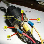
The black-and-white-striped wire from the harness goes to the negative terminal. Positive terminal gets the white wire that has a black trace. The contact breaker is connected to the black wire. If you’re not sure about the connection between the twowires, use a paper clip to remove them from the housing of the plug. Check that the terminals aren’t bent.
Accessory terminals

Diagrams of ignition wiring show the different wires that are utilized to power the vehicle’s various components. There are typically four terminals with color codes that are connected to each component. The accessories are red while the battery is yellow, the starter solenoid green. The “IGN” terminal allows you to start the car, control the wipers, and any other functions. This diagram shows how you can connect ACC and ST terminals to the rest of components.
The terminal BAT holds the battery. The battery is essential to allow the electrical system to begin. The switch won’t turn on if there is no battery present. You may refer to the wiring diagram if unsure where your car’s batteries are. The ignition switch is connected to the car’s battery. The BAT connector is connected to your battery.
Certain ignition switches come with an additional position in which users can alter their outputs and manage them without needing to use the ignition. Sometimes, customers want to make use of the auxiliary output separately from the ignition. The auxiliary output is connected by wiring the connector with the same colors as the ignition and attaching it to the ACC terminal of the switch. Although this is a fantastic feature, there’s one thing you should know. A majority of ignition switches feature an ACC position when your car is in the ACC mode and a START position when you are in IGN.
Gallery of Wiring Ignition Switch Diagram
Gallery of Wiring Ignition Switch Diagram


