Outboard Ignition Switch Wiring Diagram – Let’s begin by looking at the different kinds of terminals that are found in an ignition switch. They include terminals for Coil, Ignition Switch, and Accessory. Once we have identified what these terminals do and what they do, we can then identify the different parts in the ignition wiring. We’ll also discuss the functions as well as the Coil. The next step is to focus to the accessory terminals.
The terminals are for ignition switches.
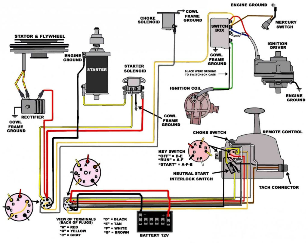
An ignition switch has three switches. They supply the voltage of the battery to many different places. The ON/OFF state of the switch that controls the ignition is managed by the first switch, which delivers power to the choke whenever it’s pushed. Different manufacturers use different colour-coding systems that correspond to the conductors. OMC utilizes this method. There is a connector inside the ignition switch to allow attaching an tachometer.
While most ignition switch terminals can be duplicated, the number may not match the diagram. Verify the continuity of the wires first to ensure that they are correctly plugged in the ignition switch. A multimeter is a great tool to test the continuity. Once you’re satisfied with the quality of the connection then you can connect the new connector. The wiring loom in an ignition system switch that is supplied by the manufacturer is different.
You must first understand the way that ACC outputs and the auxiliary outputs function in order to connect them. The ACC/IGN terminals act as the default connection on the ignition switch. The START/IGN connections connect to the radio or stereo. The ignition switch is responsible for turning the car’s engine on and off. Older cars are identified by the alphabets “ACC”, “ST”, (for individual magneto cables) on their ignition switch terminals.
Terminals for coil
To determine the type of ignition coil, the first step is to understand the definition of. In a basic diagram of the wiring for ignition there are several different terminals and connections, including two primary and two secondary. The voltage that operates on each coil differs. This is why it is essential to first check the voltage at the S1 (primary terminal). S1 must be examined for resistance to determine if the coil belongs to type A, B or C.
The coil’s low-tension end must be connected with the chassis positively. This is exactly what you can see on the diagram of wiring. The high-tension component provides the spark plugs with positive. It is essential for suppression purposes that the body of the coil’s metal be connected to its chassis but not essential. The wiring diagram will also depict the connection between positive and negative coils. In certain instances, a scan at your local auto parts shop can help you identify malfunctioning ignition coils.
The black-and-white-striped wire from the harness goes to the negative terminal. The positive terminal also gets the second white wire, which includes a black trace. The black wire goes to the contact breaker. You can check the connections using a paperclip to remove the wires of the housing. Make sure the terminals aren’t bent.
Accessory terminals
The wiring diagrams of the ignition illustrate the different wires used to provide power to the various parts of the car. There are usually four different colored terminals for each component. Red stands for accessories, yellow represents the battery and green is for the solenoid for starters. The “IGN” terminal can be utilized to turn on the car, control the wipers and other functions. The diagram shows how to connect ACC or ST terminals, and other.
The terminal BAT connects the battery to the charger. The electrical system won’t start in the event that the battery isn’t connected. Furthermore, the switch won’t start. A wiring diagram can show you where to find the battery of your car. The accessory terminals of your car connect to the battery as well as the ignition switch. The BAT terminal is connected to the battery.
Some ignition switches feature an additional “accessory” location, which allows users can manage their outputs without the ignition. Sometimes, a customer wants to make use of the auxiliary output separately from the ignition. To use the auxiliary output, wire the connector using identical colors to the ignition and connect it to the ACC terminal on the switch. Although this is a great feature, there’s something you should know. The majority of ignition switches have an ACC position if the car is in the ACC however they’ll be at the START position when the vehicle is in IGN.
Gallery of Outboard Ignition Switch Wiring Diagram
Gallery of Outboard Ignition Switch Wiring Diagram


