Gm Ignition Wiring Diagram – First, we will examine the various types of terminals found on the ignition switch. They include terminals for the Ignition switch, Coil, and Accessory. Once we understand the function of each type of terminal, we can then identify the parts of the ignition wiring. We’ll also discuss the different functions of the Ignition Switch and the Coil. Then, we’ll turn our attention to the Accessory terminals.
Terminals for ignition switch
Three switches can be found in an ignition switch. Each of these switches is able to feed the battery’s voltage to several different destinations. The first is used to power the choke by pushing it. Then, the second is for the ON/OFF position. Each manufacturer has its own color-coding system, which we will discuss in another article. OMC utilizes this system. The ignition switch is also equipped with an option to connect an Tachometer.
While some ignition switch terminals don’t have the original design, the numbering may not match the diagram. Check the electrical continuity to determine if they’re plugged into the ignition switch in the correct way. This can be checked with a simple multimeter. After you’re satisfied with the integrity of the wires you can install the new connector. If your car has an original ignition switch supplied by the factory (or a wiring loom), the wiring loom might differ from that in your car.
First, understand the differences between the ACC and secondary outputs. The ACC and IGN terminals are the default connections on your ignition switch, and the START and IGN terminals are the primary connections for stereo and radio. The ignition switch is the one that turns the car’s engine to and off. On older vehicles the terminals of the ignition switch are identified with the initials “ACC”, and “ST” (for the individual magnetic wires).
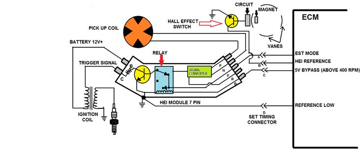
Terminals for coil
The terms used to define the type and model of the ignition coil is the primary thing. There are a variety of connections and terminals on a basic ignition wiring schematic which includes two primary as well as two secondary. The voltage that operates on every coil is different. Therefore, it is crucial to test the voltage at S1 (primary terminal). It is also recommended to test S1 for resistance to determine whether it is an A or B coil.
The chassis’ negative must be connected to the side of low-tension. This is also the ground in the wiring diagram for ignition. The high-tension supply provides positively directly to spark plugs. It is required for suppression purposes that the metallic body of the coil is connected to its chassis however it isn’t essential. It is also possible to see the connections of the positive and negative coil terminals on the diagram of the ignition wiring. It is possible to find an issue with your ignition coil which can be identified by scanning it in the auto parts shop.
The black-and-white-striped wire from the harness goes to the negative terminal. The white wire is black and goes to the terminal opposite. The contact breaker is attached to the black wire. It is possible to check the connections using a paperclip to take the wires out of the housing. Check that the terminals aren’t bent.
Accessory terminals
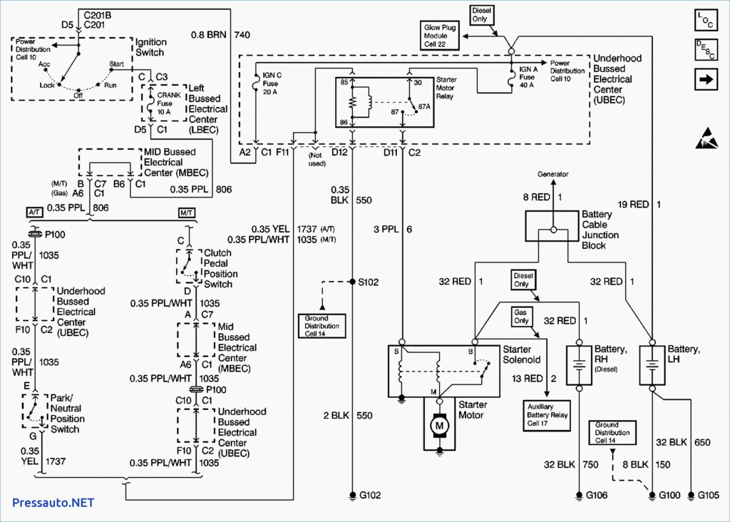
Diagrams of ignition wiring show the wires used in the vehicle’s power supply. There are usually four different colors of terminals connected to each part. The accessories are red while the battery is yellow the starter solenoid is green. The “IGN terminal lets you start your car, operate the wipers or other operation features. This diagram shows how to connect ACC and ST terminals to the rest of components.
The battery is connected to the terminal called BAT. Without the battery the electrical system will not start. Furthermore the switch isn’t turned on. You can view the wiring diagram of your car to see where the batteries of your car are situated. The accessory terminals of your car are connected with the battery and ignition button. The BAT Terminal is connected to the Battery.
Some ignition switches come with an accessory position. This lets users connect their outputs to another location without the ignition. Customers sometimes want the auxiliary output to be used independently from the ignition. The auxiliary output could be utilized by wiring the connector in the same colors as your ignition and attaching it to the ACC terminal of the switch. This is a useful feature, but there is one important difference. Many ignition switches have an ACC position when the car is in ACC mode and a START mode when it is in IGN.
Gallery of Gm Ignition Wiring Diagram
Gallery of Gm Ignition Wiring Diagram


