69 Mustang Ignition Switch Wiring Diagram – We will first look at the various types of terminals for the ignition switch. These terminals include the Ignition switch, the Coil as well as the Accessory. Once we know what these kinds of terminals are for then we can discover the various components of the 69 Mustang Ignition Switch Wiring Diagram. We will also discuss what functions are available for the Ignition switch and the Coil. Then we’ll move on to the Accessory Terminals.
The terminals of the ignition switch
The ignition switch has three switches. They feed the voltage of the battery to many different places. The first switch powers the choke. The third switch regulates the ON/OFF function of the ignition switch. Different manufacturers have different color-coding systems that correspond to the conductors. OMC utilizes this approach. The ignition switch comes with an option to connect an Tachometer.
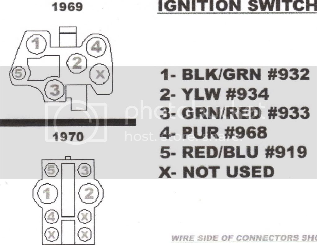
Even though some ignition switch terminals don’t come in original form however, the numbers may not be in line with the diagram. To make sure that your wires are plugged in to the ignition switch, you must verify their continuity. This can be done with an inexpensive multimeter. Once you’ve verified that the wires are in good condition, you are able to install the connector. If your car has an original factory-supplied ignition switch (or an electrical loom), the wiring loom will differ from the one in the car.
In order to connect the ACC outputs to the auxiliary outputs on your vehicle, you have first know the way these two connections function. The ACC, IGN and START terminals are the default connection to the ignition switch. They also function as the main connections to the radio and stereo. The ignition switch regulates the engine in your car. On older cars the ignition switch’s terminals are marked with the letters “ACC” as well as “ST” (for the individual magnetic wires).
Terminals for coil
To determine the type of ignition coil you need to know the step is to know the definition of. The fundamental diagram of ignition wiring shows a number different connections and terminals. There are two primary and one secondary. It is essential to identify the kind of coil you own by examining the voltage at the primary terminal S1. S1 must be checked for resistance to identify if the coil belongs to type A, B or C.
The coil’s low-tension side must be connected to the chassis positive. It is also the ground on an ignition wiring diagram. The high-tension side supplies the positive power directly to the spark plugs. For suppression purposes the coil’s body metal must be connected with the chassis. This is not necessary for electrical use. The diagram of the ignition wiring will also demonstrate the connections between the negative and positive coil terminals. Sometimes, an inspection at an auto part store can detect a defective ignition wire.
The black-and-white-striped wire from the harness goes to the negative terminal. The other white wire has a black trace on it and connects to the positive terminal. The black wire connects to the contactbreaker. To confirm the connections, make use of a paperclip or pencil to remove them from the plug housing. It is also important to see that the terminals aren’t bent.
Accessory terminals
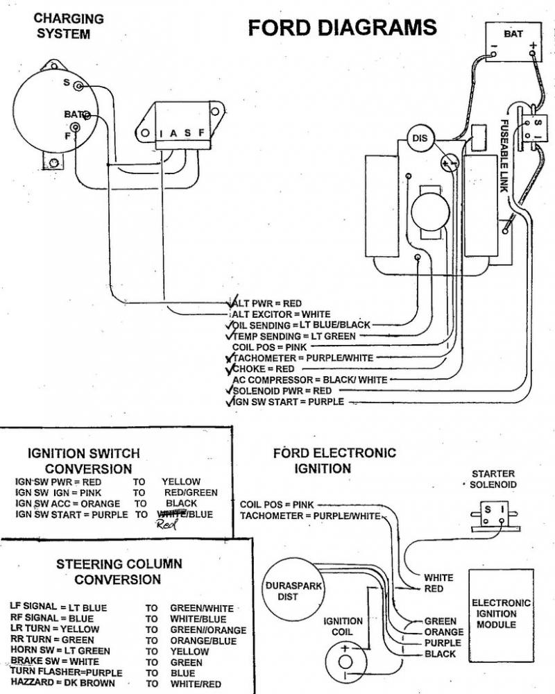
Diagrams of ignition wiring show the various wires used to power the car’s various components. There are typically four different colors-coded terminus of each part. To identify accessories, red stands for starter solenoid, blue for battery, and blue for accessories. The “IGN terminal is used for starting the car, controlling the wipers, and for other functions. The below diagram shows how to connect the ACC terminal and ST terminals to the other components.
The terminal BAT holds the battery. The battery is necessary to allow the electrical system to get started. The switch won’t be able to turn on if the battery isn’t present. To find the battery in your car examine the wiring diagram. The accessory terminals on your car are connected to the battery as well as the ignition switch. The BAT connector is connected to your battery.
Some ignition switches come with an additional position. This allows users to access their outputs from a different location without the ignition. Sometimes, customers may wish to utilize the auxiliary input independently of the ignition. To make use of the auxiliary output, wire the connector in the same colors as ignition connecting it to the ACC terminal on the switch. While this is a convenient feature, there is one crucial distinction. The majority of ignition switches are configured to show an ACC status when the car is at either the ACC or START position.
Gallery of 69 Mustang Ignition Switch Wiring Diagram
Gallery of 69 Mustang Ignition Switch Wiring Diagram


