Hot Wire Kawasaki Ninja Ignition Wiring Diagram – We’ll begin by looking at the various types of terminals in an ignition switch. These terminals are used for the Ignition button, Coil and Accessory. Once we know the purpose of each kind of terminal, we can then determine the components of the ignition wiring. In addition, we will discuss the roles of both the Ignition Switch and Coil. We will then discuss the function of the Ignition switch and Coil.
Terminals of ignition switch
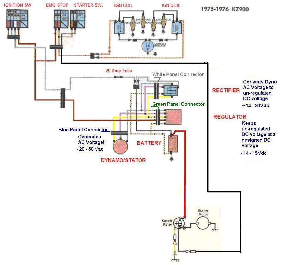
The ignition switch has three switches. They feed the voltage of the battery to different locations. The choke is powered by the first switch. The third switch regulates the ON/OFF of the ignition switch. Every manufacturer has its unique color-coding system, which we’ll discuss in a subsequent article. OMC employs this system. A connector is also included in the ignition switch to allow connecting a Tachometer.
Although the majority of ignition switch terminals can be duplicated, the numbers may not be consistent with the diagram. To make sure that your wires are connected to the ignition switch, you must verify their continuity. This can be checked using a simple multimeter. When you are satisfied with the integrity of the wires, it is time to install the new connector. If your vehicle has an ignition switch installed the wiring diagram may differ.
Before you can connect the ACC outputs to your car’s auxiliary outputs it is crucial to know the fundamentals of these connections. The ACC terminals and IGN terminals are the primary connections to the ignition switch. The START and IGN connections are the main connections for radio and stereo. The ignition switch turns the car’s engine ON and OFF. The terminals of the ignition switch on older vehicles are marked with the initials “ACC” and “ST” (for the individual magneto wires).
Terminals for coil
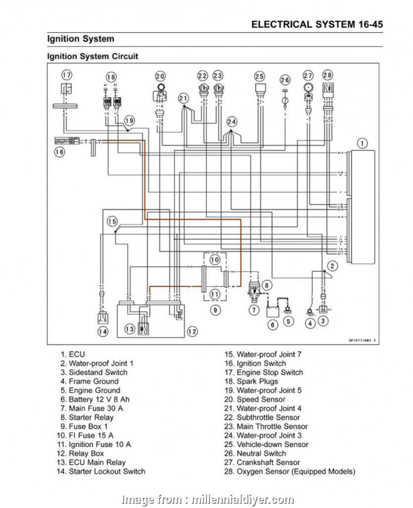
The first step to determine the type of ignition coil is to comprehend the terms employed. You’ll see a number of connections and terminals within an ignition wiring schematic, including two primary, and two secondary. The coils come with a distinct operating voltage, and the first step to determine which one you’ve got is to check the voltage of S1 the primary terminal. S1 should also be checked for resistance in order to identify whether it’s an A, Type B, or an A coil.
The low-tension end of the coil needs to be connected to the chassis’ negative. This is what you see in the wiring diagram. The high-tension side supplies positive direct to the sparkplugs. For suppression purposes the coil’s body metal must be connected to the chassis. This is not necessary to use electricity. The wiring diagram will also show the connection between the positive and negative coils. Sometimes, a damaged ignition coil can be detected through a scan performed at an auto parts shop.
The black-and-white-striped wire from the harness goes to the negative terminal. The other white wire is black and goes to the negative terminal. The black wire connects to the contact breaker. It is possible to remove the black wire from the housing of the plug with a paper clip in case you are uncertain about the connection. Make sure that the connectors aren’t bent.
Accessory terminals
The ignition wiring diagrams illustrate the various wires that power the various components of the car. Each component is equipped with four distinct connections that are color coded. The accessories are colored red, the battery is yellow, the starter solenoid green. The “IGN” terminal can be utilized to turn on the car, operate the wipers, and other functions. The diagram illustrates the connection between the ACCand ST terminals.
The terminal BAT is where the battery is. The battery is necessary to allow the electrical system to get started. The switch will not turn on if there is no battery there. A wiring diagram can tell you where to find the battery in your car. The accessory terminals of your car are connected to the battery and the ignition button. The BAT terminal is connected to the battery.
Some ignition switches come with the option of an “accessory position” that lets users adjust their outputs independently of the ignition. Sometimes, customers wish to use an auxiliary output that is separate from the ignition. Make use of the secondary output by connecting it to the ACC terminal on your switch that has the same color. Although this is a useful feature, there is one crucial distinction. A majority of ignition switches feature an ACC position when the car is in ACC mode, and a START position when the switch is in IGN.
Gallery of Hot Wire Kawasaki Ninja Ignition Wiring Diagram
Gallery of Hot Wire Kawasaki Ninja Ignition Wiring Diagram


