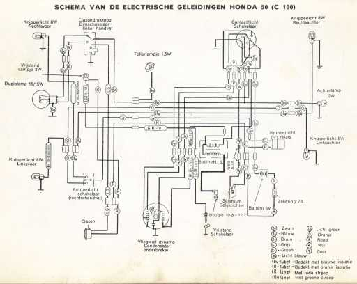
Honda Ignition Wiring Diagram – The first step is to examine the different types of terminals that are used on the ignition switch. These terminals comprise the Ignition switch, the Coil along with the Accessory. When we have a clear understanding of the purpose of each type of terminal, we can then identify the parts of the ignition wiring. We will also cover the roles of both the Ignition Switch and the Coil. After that we will proceed to the Accessory Terminals.
Terminals for ignition switch
The ignition switch is comprised of three separate switches that feed the battery’s current to various locations. The ON/OFF position of the ignition switch is controlled by the second switch, which supplies power to the choke when it’s pushed. Different manufacturers have different color-coding schemes for different conductors. We will cover this in a different article. OMC employs this system. The adapter is attached to the ignition switch to allow for the addition of a tachometer.
Although most ignition switch terminals can be duplicated, the number may not match the diagram. Check the continuity of all wires to ensure they are correctly connected to the ignition switches. This can be done with a simple multimeter. Once you are satisfied with the continuity of the wires connect the new connector. If your vehicle has an original ignition switch supplied by the factory (or a wiring loom) the wiring loom might differ from that in your vehicle.
Before connecting the ACC outputs to your car’s auxiliary outputs It is essential to be familiar with the fundamentals of these connections. The ACC and IGN terminals are the default connection on the ignition switch. the START and IGN terminals are the primary connections for the stereo and radio. The ignition switch regulates the engine in your car. The terminals on older cars ignition switches are marked by “ACC” as well as ST (for specific magneto wires).
Terminals for coil
Understanding the terms is the first step in knowing what type of ignition coil you own. A simple diagram of the wiring will display a range of terminals and connections, including two primary and two secondaries. The coils come with a distinct operating voltage. The initial method of determining what type you’ve got is to check the voltage at S1, the primary terminal. S1 must also be subjected to resistance testing to determine if it are a Type A or B coil.
The coil’s low-tension component is to be connected to the chassis positive. This is also the ground on the diagram of ignition wiring. The high-tension end supplies positive direct to the sparkplugs. It is required for suppression purposes that the coil’s metallic body be connected to its chassis, however it isn’t essential. There are also connections between the positive and negative coil’s terminals on an diagram of the ignition wiring. Sometimes, a visit to an auto parts store could diagnose a malfunctioning ignition wire.
The black-and-white-striped wire from the harness goes to the negative terminal. The positive terminal receives the white wire, which has the black trace. The black wire goes to the contact breaker. You can take the black wire from the housing of the plug with a paper clip If you’re unsure of the connection. Make sure that the terminals don’t bend.
Accessory terminals
Ignition wiring diagrams depict the various wires utilized to power the various components. In general there are four colors-coded terminals that are used for each component. Red is used for accessories and yellow is for the battery, while green is the starter solenoid. The “IGN” terminal is used to start the car and operate the wipers as well as other operational functions. The following diagram shows how to connect both the ACC terminal and ST terminals to other components.
The terminal BAT is where the battery is. The electrical system can’t be started without the battery. In addition the switch won’t come on. If you’re not sure of the location of your car’s battery situated, you can examine the wiring diagram of your car to determine the best way to find it. The ignition switch is connected to the car’s battery. The BAT connector is connected to the battery.
Some ignition switches are equipped with an additional position. This lets users connect their outputs to a different location without having to turn on the ignition. Customers may want to utilize the auxiliary output separately from the ignition. To make use of the auxiliary output, wire the connector using the same colors as the ignition connecting it to the ACC terminal on the switch. This is a great feature, but there is an important difference. The majority of ignition switches are set to operate in the ACC position when the vehicle is in the ACC position, whereas they’re in the START position when the car is in the IGN position.
Gallery of Honda Ignition Wiring Diagram
Gallery of Honda Ignition Wiring Diagram


