Points Ignition System Wiring Diagram – We will first examine the different types of terminals for the ignition switch. These are the terminals used that are used for Coil, Ignition Switch, and Accessory. Once we know the terminals that are utilized and which ones are not, we can identify the different components of the Points Ignition System Wiring Diagram. We will also discuss the functions of the Ignition switch and Coil. Then, we’ll focus on the accessory terminals.
Terminals for the ignition switch
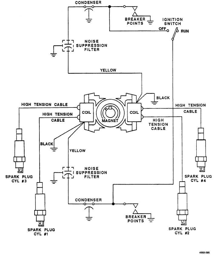
Three switches can be found on an ignition switch. Each of these switches transmits the battery’s current to various destinations. The ON/OFF state of the switch that controls the ignition is managed by the first switch, which supplies power to the choke whenever it’s pushed. Different manufacturers utilize their own color-coding method for the various conductors, that is described in a separate article. OMC utilizes this method. The ignition switch is also equipped with a connector for adding the Tachometer.
Although most ignition switch terminals can be duplicated, the number may not be in line with the diagram. Check the electrical continuity first to make sure they’re properly connected to the ignition switch. A multimeter is a great instrument to verify the continuity. When you’re satisfied with the continuity of the wires, then you’ll be able to install the new connector. The wiring loom for the ignition switch supplied by the manufacturer will differ from the one you have in your vehicle.
For connecting the ACC outputs to the auxiliary outputs on your car, you’ll need to first understand the way these two connections function. The ACC and IGN terminals are the default connection on your ignition switch. the START and IGN terminals are the main connections to the radio and stereo. The ignition switch is the one that controls the engine of your car. The terminals of older cars ignition switches are marked by “ACC” as well as ST (for the individual magneto wires).
Coil terminals
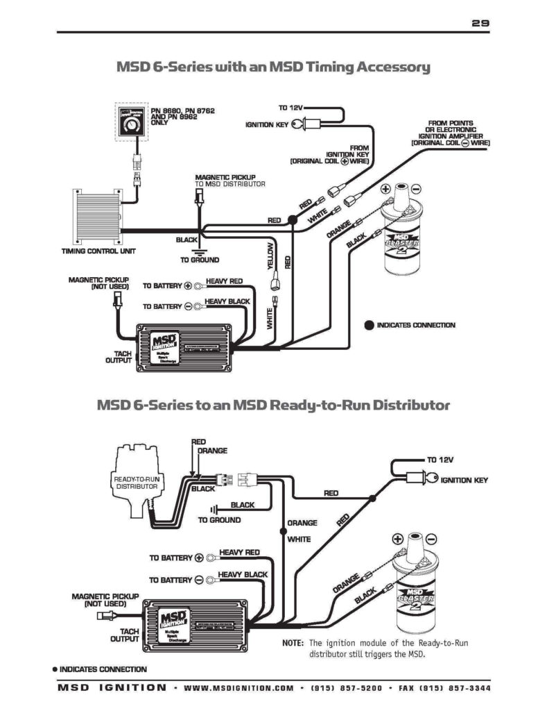
The language used to decide the model and type of the ignition coil is the primary thing. A basic ignition wiring layout will provide you with a range of connections and terminals. Each coil operates at a specific voltage. The first step to determine the type you’re dealing with is to test the voltage at S1 or the primary terminal. To determine if it is an A, C, or B coil, you must also check the resistance of S1.
The chassis’ negative needs to be connected to the low-tension side. This is the base of the ignition wiring. The high tension part supplies positive directly the spark plugs. To prevent noise, the coil’s metal body must be connected to the chassis. But, it’s not required to connect electrically. The wiring diagram of the ignition will explain how to connect the terminals of either the positive or negative coils. Sometimes, a visit to an auto parts shop can detect a defective ignition wire.
The black-and-white-striped wire from the harness goes to the negative terminal. The other white wire is black and connects to the terminal opposite. The black wire connects to the contact breaker. If you’re not certain about the connections of the twowires, use an old paper clip to take them from the plug housing. Be sure that the terminals aren’t bent.
Accessory terminals
Diagrams of ignition wiring show the different wires that are utilized to power the vehicle’s various components. Each component has four distinct connections that are color coded. The red color is used for accessories, yellow is for the battery, and green is the starter solenoid. The “IGN” terminal can be used to start the car , and also to operate the wipers, as well as other operating functions. The diagram demonstrates how to connect the ACC and ST terminals to the rest of the components.
The terminal BAT is the connection for the battery. The battery is necessary for the electrical system to get started. Additionally, the switch will not start without the battery. To find your car’s battery look over your wiring diagram. The accessory terminals in your car connect to the ignition switch and the battery. The BAT terminal is connected to the battery.
Certain ignition switches have an additional “accessory” position, where users can manage their outputs without using the ignition. Sometimes, users want to use an auxiliary output that is not connected to the ignition. You can use the auxiliary output by connecting it to an ACC terminal on the switch using the same colors. This is an excellent feature, however there’s one important distinction. A majority of ignition switches feature the ACC position when the car is in ACC mode and a START mode when the switch is in IGN.
Gallery of Points Ignition System Wiring Diagram
Gallery of Points Ignition System Wiring Diagram


