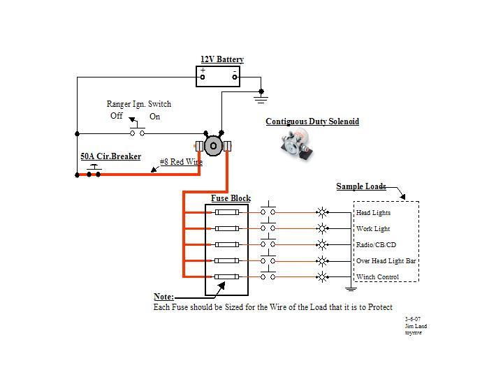
Polaris Ranger Ignition Wiring Diagram – We’ll begin by looking at the various kinds of terminals that are found in an ignition switch. These are the terminals used that are used for Coil, Ignition Switch, and Accessory. When we have a clear understanding of the purpose of each terminal, it is possible to determine the components of the ignition wiring. We will also cover the different functions of the Ignition Switch and the Coil. After that we will proceed to the Accessory Terminals.
Terminals of ignition switch
An ignition switch is comprised of three switches. They transmit the battery’s voltage to many different places. The first is used to power the choke by pushing it. Then, the second is for the ON/OFF setting. Different manufacturers have different color-coding schemes for different conductors. This will be covered in a separate article. OMC uses this system. The connector allows for the attachment of a speedometer to the ignition switch.
While many ignition switch terminals do not come in original form however, the numbers may not match the diagram. First, check the continuity of all the wires to ensure they are correctly plugged into the ignition switches. This can be done using a simple multimeter. When you’re satisfied with the integrity of your wires, you will be able install the new connector. If your car has an original factory-supplied ignition switch (or an electrical loom) the wiring loom might differ from that of your vehicle.
It is essential to know how the ACC outputs and the auxiliary outputs function in order to connect them. The ACC/IGN terminals act as the default connections for the ignition switch. The START/IGN connections connect to the stereo or radio. The ignition switch controls the car’s engine. Older cars have the ignition switch terminals marked “ACC” or “ST” (for individual magnetowires).
Terminals for coil
The first step to determine the type of ignition coil is to comprehend the terms that is used. You’ll see a number of connections and terminals in an ignition wiring schematic which includes two primary and two secondary. The operating voltage of each coil differs. This is why it is important to first test the voltage at the S1 (primary terminal). You should also examine S1 for resistance to identify if it’s an A B, C, or coil.
The low-tension coil side must be connected to the chassis’ plus. This is the ground of the wiring for ignition. The high-tension part supplies the spark plugs with positive. The metal body of the coil needs to connect to the chassis to suppress the effect however it isn’t electrically necessary. The wiring diagram for the ignition will explain how to connect the two terminals of the negative or positive coils. In some instances, you’ll find that an ignition coil that is malfunctioning can be diagnosed with scanning in an auto parts store.
The black-and-white-striped wire from the harness goes to the negative terminal. The positive terminal receives the other white wire with an trace in black. The black wire connects to the contact breaker. To check the connections, you can employ a paperclip, or a pencil to remove them of the plug housing. Make sure that the terminals don’t bend.
Accessory terminals
The wiring diagrams for the ignition show the various wires that power the various components of the vehicle. There are typically four colored terminals for each component. Accessories are red and the battery yellow the starter solenoid green. The “IGN terminal lets you start the car, control the wipers or other operation features. The diagram shows the connections between the ACCand ST terminals.
The terminal BAT holds the battery. The electrical system will not start if the battery isn’t connected. In addition, the switch will not begin to turn on. It is possible to look up the wiring diagram of your car to see where the batteries of your car are situated. The accessory terminals of your car are connected with the battery and the ignition button. The BAT terminal is connected to the battery.
Some ignition switches offer the option of an “accessory position” that lets users adjust their outputs independently of the ignition. Customers may want to use the auxiliary output separately from the ignition. The auxiliary output can be used to connect the connector with the same colors as the ignition and connecting it to the ACC terminal of the switch. This feature of convenience is fantastic, but there is one differentiator. Many ignition switches can be set to have an ACC location when the car is in the ACC position. They’ll also be in the START position when the vehicle has entered the IGN position.
Gallery of Polaris Ranger Ignition Wiring Diagram
Gallery of Polaris Ranger Ignition Wiring Diagram


