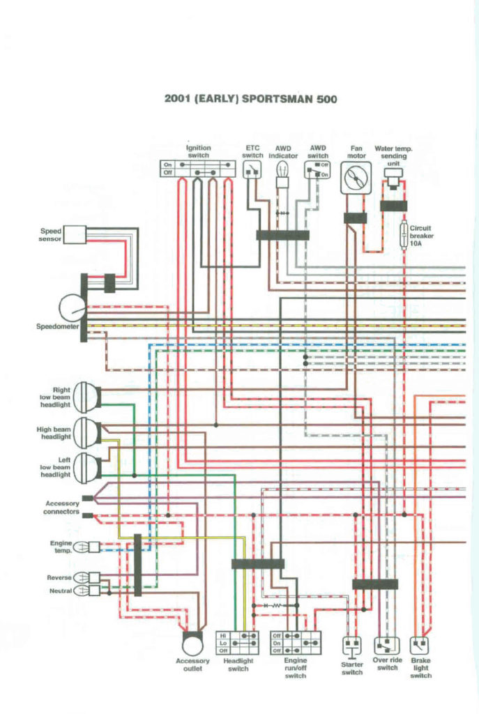
Polaris Sportsman 500 Ignition Wiring Diagram – In the beginning, we’ll examine the various types of terminals that are found in the ignition switch. These terminals comprise the Ignition switch, the Coil along with the Accessory. Once we’ve established the purpose of these terminals, we will be able to determine the various components of the ignition wiring. We will also discuss the function of the Ignition switch and Coil. Then, we’ll turn our attention to the Accessory terminals.
Terminals for the ignition switch
An ignition switch has three switches. They transmit the battery’s voltage to different locations. The first switch powers the choke. The second switch is responsible for the ON/OFF switch of the ignition switch. Different manufacturers have various color codes for the different conductors. This is explained in another article. OMC utilizes the same system. The adapter is attached to the ignition switch that allows the addition of an Tachometer.
Although some ignition switch terminals do not have the original design The numbering might not be in line with the diagram. To make sure that your wires are connected to the switch it is recommended to check their continuity. You can do this with a simple multimeter. Once you are satisfied with the continuity of the wires it is time to connect the new connector. If your car has an ignition switch that is installed the wiring diagram will differ.
Understanding how ACC outputs are connected to the auxiliary outputs in your car is essential. The ACC and IGN terminals are the default connections on your ignition switch, and the START and IGN terminals are the principal connections for stereo and radio. The ignition switch switches the car’s engine ON and off. The terminals of older cars ignition switches are marked with “ACC” and ST (for specific magneto wires).
Terminals for coil
The first step to determine the kind of ignition coil is to understand the terminology used. An ignition wiring diagram will reveal a variety of terminals and connections, comprising two primary and two secondary. The coils have a specific operating voltage, and the first step to determine which one you’re using is to test the voltage at S1, the main terminal. You should also check S1 for resistance to determine whether it is an A B, C, or coil.
The negative end of the chassis should be connected to connect the coil’s low-tension side. This is what you find in the wiring diagram. The high-tension end is a positive connection to the sparkplugs. It is required for the purpose of suppression that the coil’s metallic body be connected to its chassis, but not essential. The wiring diagram of the ignition will show you how to connect the two terminals of the positive and negative coils. Sometimes, a check at an auto part store can detect a defective ignition wire.
The black-and-white-striped wire from the harness goes to the negative terminal. Positive terminal receives a second white wire, which is black in its trace. The black wire connects to the contact breaker. To confirm the connection, employ a paperclip, or a pencil to remove them of the plug housing. Make sure that the connectors do not bend.
Accessory Terminals
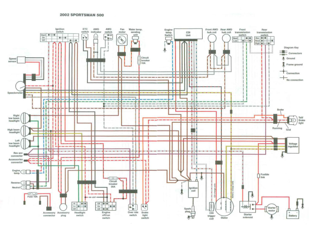
The ignition wiring diagrams illustrate the different wires that are utilized to power the vehicle’s various parts. There are usually four color-coded terminus for each component. The red color is used for accessories and yellow is for the battery, and green is for the starter solenoid. The “IGN terminal allows you to start the car, control the wipers, or any other functions. The below diagram shows how to connect both the ACC terminal and ST terminals to various components.
The battery is connected to the terminal called BAT. The electrical system will not start when the battery isn’t connected. Additionally, the switch will not turn on without the battery. You may refer to the wiring diagram if not sure where the batteries of your car are. The ignition switch is connected to the car’s battery. The BAT terminal is connected to the battery.
Some ignition switches offer an additional “accessory position” that allows users to modify their outputs independent of the ignition. Users may wish to utilize the auxiliary output in addition to the ignition. Make use of the additional output by connecting it to the ACC terminal on your switch with the same colors. This is an excellent feature, but there is one important difference. The majority of ignition switches are set to have an ACC position when the car is in the ACC position, while they’re in the START position when the car is in the IGN position.
Gallery of Polaris Sportsman 500 Ignition Wiring Diagram
Gallery of Polaris Sportsman 500 Ignition Wiring Diagram


