Prime Line Ignition Switch Wiring Diagram – The first step is to look at the different terminals that are used in the ignition switch. These terminals comprise the Ignition switch and Coil and the Accessory. Once we’ve determined the function of these terminals, it is possible to recognize the various parts of the ignition wiring. We’ll also be discussing the roles of the Ignition switch, as well as the Coil. Following that, we’ll shift our attention to Accessory terminals.
Terminals for ignition switches
An ignition switch contains three different switches that direct the battery’s current to different locations. The choke is powered by the first switch. The second switch controls the ON/OFF function of the ignition switch. Each manufacturer has its individual color-coding system that we’ll discuss in a subsequent article. OMC utilizes this method. Connectors can be attached to the ignition switch to add an electronic Tachometer.
Although some ignition switch terminals might not be original, the numbers of each may not be in line with the diagram. Before plugging into the ignition switch, ensure that you check the continuity. This can be checked using a cheap multimeter. When you are happy with the continuity of the wires, connect the new connector. The wiring loom of an ignition switch that is factory-supplied will be different than the one that you have in your car.
You must first understand the ways in which the ACC outputs and auxiliary outputs function to connect them. The ACC and IGN terminals are the default connections for the ignition switch. the START and IGN terminals are the principal connections for the stereo and radio. The ignition switch turns the engine of your car ON and off. The terminals on older cars ignition switches are marked with “ACC” as well as ST (for individual magneto wires).
Terminals for coil
Understanding the terminology that is used is the initial step to finding out the right kind of ignition coil to choose. A basic diagram of the wiring will reveal a variety of connections and terminals. Each coil is operating at a certain voltage. The first step to determine which kind you’re using is to examine the voltage at S1 or the primary terminal. To determine if the coil is a Type A, C, or B coil you should also test the resistance on S1’s.
The low-tension coil side must be connected at the chassis’ plus. It is also the ground for an ignition wiring diagram. The high-tension component supplies the spark plugs with positive. It is required for suppression purposes that the metallic body of the coil is connected to the chassis, however it isn’t essential. The wiring diagram will also illustrate the connection between the positive and negative coil terminals. Sometimes, an inspection at an auto part store can identify a problem with the ignition wire.
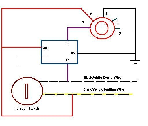
The black-and-white-striped wire from the harness goes to the negative terminal. The terminal that is negative is served by the trace in black that’s joined to the white wire. The black wire connects to the contact breaker. You can remove the black wire from the plug housing with a paper clip if you are unsure about the connection. It is also important to make sure the terminals do not bend.
Accessory terminals
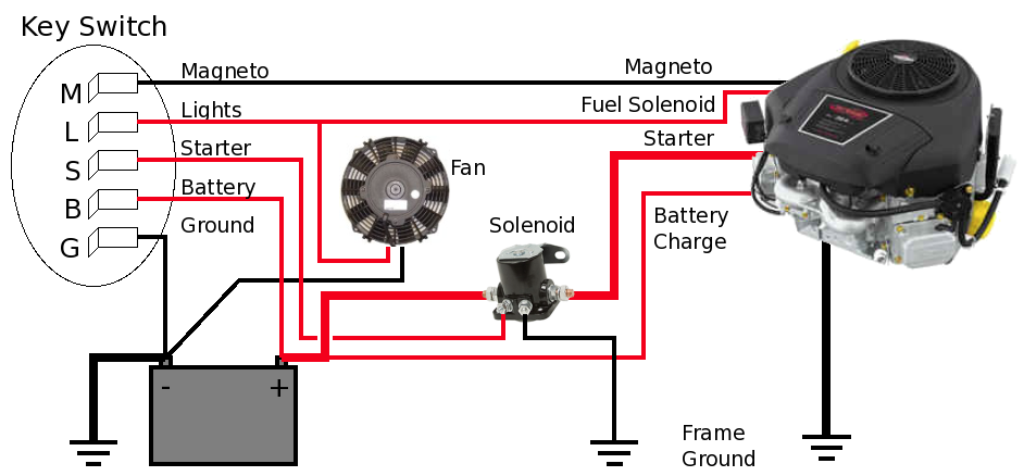
Diagrams of ignition wiring show the various wires utilized to power the vehicle’s various parts. In general there are four colored terminals for each part. Red is for accessories while yellow is the battery, while green is for the solenoid for starters. The “IGN” terminal is used to start the car , and also to operate the wipers as well as other operational features. The diagram shows how you can connect the ACC and ST terminals to the other components.
The terminal BAT is the connection to the battery. The battery is vital for the electrical system to start. In addition, the switch will not begin to turn on. It is possible to look up your wiring diagram to figure out where your car’s batteries are located. The ignition switch is connected to the battery of your car. The BAT connector is connected to your battery.
Some ignition switches come with an additional position. It allows users to access their outputs from another location without the ignition. Sometimes, customers would like the output of the auxiliary to be used independently from the ignition. You can use the secondary output by connecting it to the ACC terminal on your switch that has the same color. Although this is a great feature, there’s something you should know. Most ignition switches are set to be in an ACC position when the vehicle is in the ACC position, while they’re set to the START position when the vehicle is in the IGN position.
Gallery of Prime Line Ignition Switch Wiring Diagram
Gallery of Prime Line Ignition Switch Wiring Diagram


