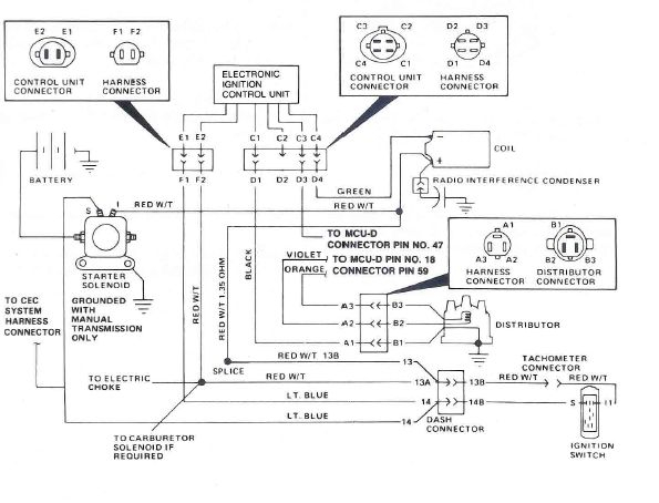
97 Dodge Ram Ignition Switch Wiring Diagram – We will first examine the different types of terminals that are used on the ignition switch. These are the terminals that connect the Ignition, Coil, or Accessory. Once we’ve determined the function of these terminals, we will be able to identify the various parts of the ignition wiring. We’ll also discuss the functions as well as the Coil. Then, we will concentrate on the accessories terminals.
Terminals for ignition switches
An ignition switch is comprised of three switches. They transmit the voltage of the battery to many different places. The first one is used to power the choke by pushing it, and another switch controls the ON/OFF position. Different manufacturers use various color codes for the different conductors. This is explained in another article. OMC utilizes this method. The connector allows for the attachment of a speedometer the ignition switch.
Although most ignition switch terminals can be duplicated, the number may not be in line with the diagram. It is important to first verify the continuity of the wires to ensure that they are plugged into the ignition switch in the correct way. This can be done using a simple multimeter. Once you’ve verified that the wires are in good condition, you can install the connector. The wiring loom used in a factory-supplied ignition system switch is distinct.
The first step is to understand the distinctions between the ACC and auxiliary outputs. The ACC and IGN connectors are the standard connections for your ignition switch. Although the START, IGN, and ACC terminals are the primary connections for radios or stereo, the START/IGN connections are the main ones. The ignition switch is the engine’s on/off button. The terminals of older vehicles ignition switches are marked by “ACC” and ST (for specific magneto wires).
Coil terminals
Understanding the terms is the initial step in determining which type of ignition coil you’ve got. You’ll see a number of connections and terminals in an ignition wiring schematic which includes two primary and two secondary. You must determine the type of coil that you have by testing the voltage at the primary terminal, S1. S1 should also be tested for resistance in order to identify whether it’s a Type B, B, or A coil.
The lower-tension side of the coil must be connected to the chassis’ negative. This is also the ground in the ignition wiring diagram. The high-tension supply supplies positive directly to spark plugs. To prevent noise, the coil’s body metal is required to be connected to the chassis. It’s not necessary for electrical use. The ignition wiring diagram will also indicate how to connect the positive coil’s terminals. There could be an issue with your ignition coil that can be easily diagnosed by looking it up at an auto parts store.
The black-and-white-striped wire from the harness goes to the negative terminal. The positive terminal also receives the white wire that is black in its trace. The black wire is connected to the contact breaker. To confirm the connections, you can employ a paperclip, or a pencil to remove them of the housing for the plug. Also, make sure to ensure that the terminals haven’t been bent.
Accessory terminals
Diagrams of the ignition wiring illustrate the wires used to provide power to various components of the vehicle. Typically there are four color-coded terminals for each component. The red color is used for accessories while yellow is the battery, and green is the starter solenoid. The “IGN terminal lets you start the car, control the wipers, and any other functions. This diagram demonstrates how to connect ACC and ST terminals to the rest of components.
The terminal BAT is the connection to the battery. The electrical system is not able to start without the battery. Additionally the switch isn’t turned on. You may refer to the wiring diagram if uncertain about where the car’s batteries are located. The ignition switch is linked to the car’s battery. The BAT connector is connected to your battery.
Some ignition switches include an accessory setting where users can modify their outputs as well as control them without having to turn on the ignition. Users may wish to utilize the auxiliary output independently of the ignition. It is possible to use the auxiliary input by connecting it to the ACC terminal. Although this is a fantastic option, there’s a thing you need to know. Most ignition switches are designed to show an ACC status when the car is in either the ACC or START position.
Gallery of 97 Dodge Ram Ignition Switch Wiring Diagram
Gallery of 97 Dodge Ram Ignition Switch Wiring Diagram


