Push Button Ignition Wiring Diagram – In the beginning, we’ll take a look at the various kinds of terminals in the ignition switch. These are the terminals that connect the Ignition, Coil, or Accessory. After we’ve identified the purpose of these terminals, it is possible to recognize the various parts of the ignition wiring. Then, we will discuss what functions are available for the Ignition switch and the Coil. We’ll then turn our attention to the accessory terminals.
The terminals of the ignition switch

Three switches are located in an ignition switch. Each of the three switches is able to feed the battery’s voltage to several different locations. The first is utilized to power the choke through pushing it, while the third switch is used to control the ON/OFF position. Different manufacturers use their own color-coding systems for different conductors which is documented in another article. OMC utilizes this method. The ignition switch comes with an adapter for the addition of the timer.
Although some ignition switch terminals might not be original, the numbering of each may not be in line with the diagram. You should first check the integrity of the wires to determine if they’re plugged into the correct ignition switch. This can be checked using an inexpensive multimeter. After you’re satisfied with the continuity of the wires, it is time to install the new connector. If you’re using a factory-supplied ignition switch, the wiring loom is different from the one you have in your car.
In order to connect the ACC outputs to the auxiliary outputs on your car, you’ll need first know the way these two connections function. The ACC and IGN terminals are the default connection on the ignition switch. the START and IGN terminals are the principal connections for the stereo and radio. The ignition switch controls the car’s engine. The terminals on older cars ignition switches are identified by “ACC” as well as ST (for individual magneto wires).
Terminals for coil
The terminology used to determine the model and type of an ignition coil is the most important thing. The fundamental diagram of ignition wiring shows a number different connections and terminals. There are two primary and one secondary. Each coil is equipped with a distinct operating voltage. To determine which type of coil you’ve got first, you need to test the voltage at S1, which is the primary terminal. To determine whether it’s a Type A, C or B coil, you should also test the resistance on S1’s.
The low-tension coil side must be connected at the chassis’ less. This is the ground of the ignition wiring. The high tension side provides positively directly to the spark plugs. The aluminum body of the coil needs to be connected to the chassis for suppression, but it isn’t electrically required. The diagram of the ignition wiring will also show the connection of the positive coil terminals. There could be an ignition coil problem that can be easily diagnosed by looking it up at an auto parts store.
The black-and-white-striped wire from the harness goes to the negative terminal. The positive terminal receives the white wire, which has an black trace. The black wire is connected to the contact breaker. You can take the black wire from the housing of the plug by using a paperclip If you’re unsure of the connections. Make sure that the connectors don’t bend.
Accessory terminals
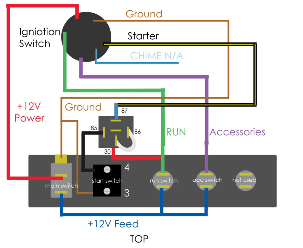
Diagrams of the ignition wiring show the wires that power various parts of the vehicle. There are usually four terminals with color codes that are connected to the component. For accessories, red is the starter solenoid’s color, blue for battery and blue for accessory. The “IGN terminal allows you to start your car, operate the wipers or other operation features. The diagram shows the connection between the ACC- and ST terminals.
The terminal known as BAT is the location where the battery is. The electrical system will not start without the battery. A dead battery could cause the switch to stop turning on. You may refer to the wiring diagram if you’re uncertain about where the car’s batteries are. The accessory terminals in your vehicle connect to the battery and the ignition switch. The BAT Terminal is connected to the battery.
Certain ignition switches have an additional position in which users can modify their outputs and manage them without having to turn on the ignition. Some customers want an auxiliary output that can be used separately from the ignition. In order to use the additional output, wire the connector with the same colors as ignition connecting it to the ACC terminal on the switch. Although this is a great feature, there’s one thing to be aware of. The majority of ignition switches have an ACC position if the car is in the ACC, but they will be in the START position if the vehicle is IGN.
Gallery of Push Button Ignition Wiring Diagram
Gallery of Push Button Ignition Wiring Diagram


