1979 Ford F150 Ignition Wiring Diagram – We will first examine the different types of terminals for the ignition switch. These terminals comprise the Ignition switch and Coil along with the Accessory. Once we know the purpose of these terminals and what they do, we can then identify the different parts in the ignition wiring. We’ll also be discussing the functions of the Ignition switch, as well as the Coil. Next, we’ll discuss the functions of the Ignition switch as well as Coil.
Terminals for ignition switch
The ignition switch has three switches. They transmit the battery’s voltage to many different locations. The first switch provides power to the choke whenever it is pushed. The third is the switch that controls the ignition’s ON/OFF positions. Different manufacturers use various color codes for the various conductors. This is explained in another article. OMC utilizes this method. The ignition switch is also equipped with a connector for adding the Tachometer.
While the majority of ignition switch terminals don’t have an original number, they may have a different number. Before plugging into the ignition switch be sure to test the continuity. You can check this using an inexpensive multimeter. After you’re satisfied with the integrity of the wires, install the new connector. If your car has an ignition switch that is installed the wiring diagram may differ.
Before you can connect the ACC outputs to the auxiliary outputs of your car, it is important to be familiar with the fundamentals of these connections. The ACC and IGN terminals are the default connection on your ignition switch, and the START and IGN terminals are the main connections for the radio and stereo. The ignition switch is responsible to turn the engine of your car on and off. Older vehicles have ignition switch terminals labeled “ACC” or “ST” (for individual magnetowires).
Terminals for coil
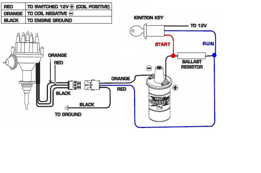
Understanding the terminology is the first step in knowing what type of ignition coil you’ve got. The diagram of the basic ignition wiring illustrates a variety of connections and terminals. There are two primary and secondary connections. Each coil comes with its own operating voltage. To determine the type of coil you’ve got the first step is to determine the voltage at S1, which is the primary terminal. S1 should be checked for resistance to identify if the coil belongs to Type A, B, or C.
The lower-tension side of the coil needs to be connected to the chassis’ negative. This is what is known as the ground for the ignition wiring. The high-tension supply provides positively directly to spark plugs. To reduce the noise, the coil’s body metal must be connected with the chassis. This is not necessary to use electricity. You will also see the connections of the positive and the negative coil’s terminals on the ignition wiring diagram. It is possible to find an issue with your ignition coil that is easily identified by scanning it at an auto parts retailer.
The black-and-white-striped wire from the harness goes to the negative terminal. The negative terminal is served by the trace in black that’s connected to the white wire. The black wire connects to the contact breaker. It is possible to check the connections using a paperclip to take the wires out of the housing. Be sure that you don’t bend the connectors.
Accessory terminals
The diagrams for ignition wiring show the wires that are used in the power supply of the vehicle. There are generally four colored terminus lines for each component. For accessories, red is for starter solenoid, blue for battery, and blue is for accessory. The “IGN terminal lets you start the car, manage the wipers, and any other operation features. The below diagram shows how to connect the ACC terminal and ST terminals to various components.
The terminal BAT is where the battery is. The electrical system will not start without the battery. The switch will not turn off if the battery isn’t there. The wiring diagram will inform you where to find the battery of your car. The accessory terminals of your car connect to the ignition switch and the battery. The BAT Terminal is connected to the battery.
Certain ignition switches come with an “accessory” setting that permits users to regulate their outputs without having to use the ignition. Customers may want to utilize the auxiliary output in addition to the ignition. Use the additional output by connecting the connector to the ACC terminal on the switch that has the same color. Although this is a fantastic feature, there’s one thing to be aware of. A lot of ignition switches can be programmed to have an ACC position once the car has been moved into the ACC position. They also will be in the START mode after the vehicle has been moved into the IGN position.
Gallery of 1979 Ford F150 Ignition Wiring Diagram
Gallery of 1979 Ford F150 Ignition Wiring Diagram


