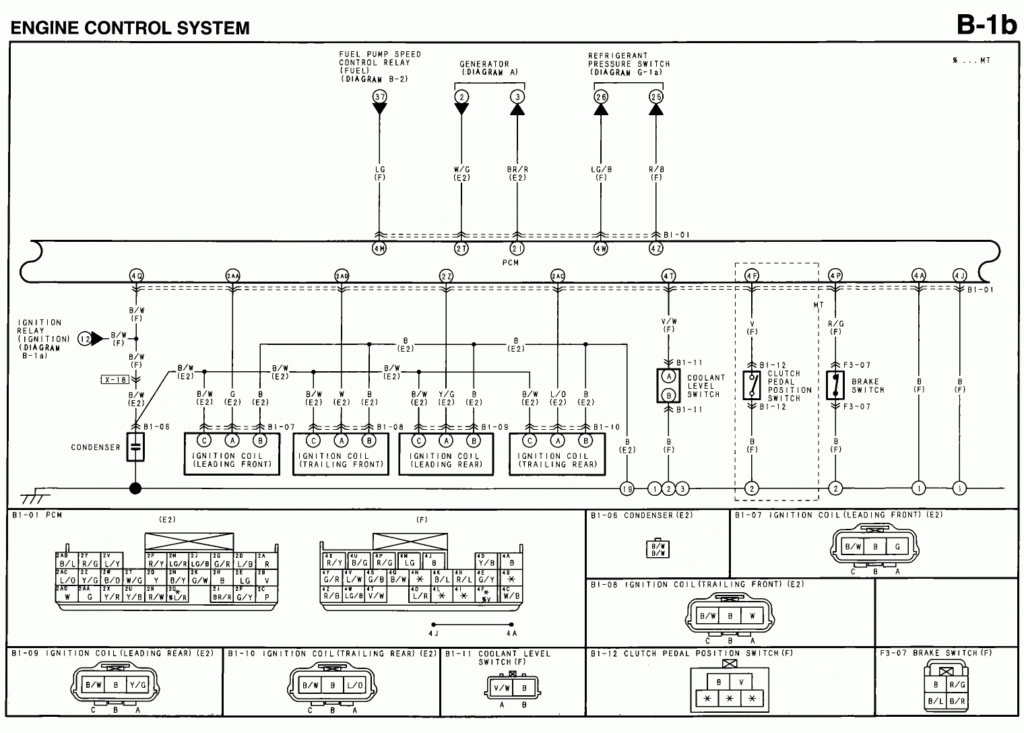
Rx8 Ignition Wiring Diagram – Let’s begin by examining the different kinds and functions of terminals found in the ignition switches. These are the terminals that connect the Ignition, Coil, or Accessory. After we’ve established the purpose of these terminals are then we can determine the various parts of the Rx8 Ignition Wiring Diagram. In addition, we will discuss the roles of the Ignition switch and Coil. We will then discuss the roles of the Ignition switch and Coil.
Terminals for ignition switch
Three switches can be found in an ignition switch. Each of these switches transmits the battery’s current to a variety of places. The ON/OFF state of the ignition switch is controlled by the first switch, which supplies power to the choke when it’s pulled. Different manufacturers use various color codes for the various conductors. This is described in a different article. OMC follows this system. The ignition switch also includes an adapter for the addition of an tachometer.
While some ignition switch terminals don’t appear in their original configuration, the numbering may not be in line with the diagram. To make sure that your wires are properly connected to the switch, you should check their continuity. This can be checked with a multimeter that is inexpensive. After you have verified the integrity of the wires you can connect the connector. If your vehicle has an ignition switch that is installed, the wiring diagram will differ.
It is essential to know the ways in which the ACC outputs and auxiliary outputs work in order to join them. The ACC, IGN and START terminals are the primary connections to the ignition switch. They also function as the main connections to the radio and stereo. The ignition switch is the one that turns the engine of your car to and off. The ignition switch terminals on older vehicles are marked with the initials “ACC” and “ST” (for individual magneto wires).
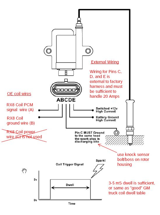
Terminals for coil
To determine the type of ignition coil, the first step is to understand the terminology. The fundamental diagram of ignition wiring shows a number different connections and terminals. There are two primary and secondary connections. You need to determine the type of coil you are using by testing the voltage at the primary terminal, S1. To determine if the coil is an A, C, or B coil, it is recommended to also check the resistance of S1.
The coil’s low-tension end must be connected with the chassis positive. It is also the ground in the diagram of ignition wiring. The high-tension component provides the spark plugs with positive. It is required for the purpose of suppression that the metallic body of the coil is connected to its chassis however, it is not necessary. The wiring diagram for ignition will also show the connection of the positive coil’s terminals. In some cases, you’ll find that a malfunctioned ignition coil is easily identified with scans in an auto parts store.
The black-and-white-striped wire from the harness goes to the negative terminal. The white wire is black-colored and connects to the negative terminal. The black wire connects to the contactbreaker. You can examine the connections using a paperclip to remove the wires of the housing. Be sure the terminals aren’t bent.
Accessory terminals
Diagrams of ignition wiring illustrate the wiring used in the vehicle’s power supply. Each component is equipped with four distinct connections that are color coded. Red is used to indicate accessories, yellow to the battery and green is the starter solenoid. The “IGN” terminal allows you to start your car, operate the wipers, and any other functions. The diagram illustrates how to connect ACC or ST terminals as well as the rest.
The terminal known as BAT is where the battery is connected. Without the battery the electrical system can not start. Furthermore the switch won’t come on. If you’re not sure the location of your car’s battery located, you can review the wiring diagram of your car to determine the best way to find it. The ignition switch is linked to the car’s battery. The BAT terminal is connected with the battery.
Some ignition switches feature an additional “accessory” position, in which users can control their outputs with no ignition. In some cases, users may want to use the auxiliary input independently of the ignition. The auxiliary output can be connected to connect the connector with the same colors as your ignition and connecting it to the ACC terminal of the switch. This is an excellent feature, but there is one important distinction. Many ignition switches can be set to have an ACC position when the vehicle has moved into the ACC position. They will also be in the START mode once the vehicle is entered the IGN position.
Gallery of Rx8 Ignition Wiring Diagram
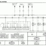
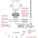
Gallery of Rx8 Ignition Wiring Diagram


