Toyota Ignition Coil Wiring Diagram – Let’s first look at the different terminals on the ignition switch. These terminals comprise the Ignition switch and Coil and the Accessory. Once we have established what these types of terminals are for then we can identify the different parts of the Toyota Ignition Coil Wiring Diagram. We will also discuss the roles of the Ignition switch and Coil. Next, we’ll discuss the roles of the Ignition switch as well as Coil.
Ignition switch terminals
The ignition switch is comprised of three switches that supply the battery’s current to various destinations. The first switch is used to power the choke through pushing it. Then, the second is for the ON/OFF position. Every manufacturer has its unique color-coding system, which we’ll go over in a separate article. OMC utilizes this method. The connector permits the connection of a speedometer to the ignition switch.
While the majority of ignition switch terminals don’t have an original number, they may be equipped with a different number. To ensure that the wires are plugged in to the ignition switch it is recommended to check their continuity. This can be accomplished using a cheap multimeter. When you are happy with the continuity of the wires it is time to install the new connector. If your car has an original factory-supplied ignition switch (or an electrical loom) The wiring loom may differ from that of the car.
Before connecting the ACC outputs to the auxiliary outputs of your car, it is important to understand the basics of these connections. The ACC, IGN and START terminals are the default connection to the ignition switch. They also function as the primary connections to the radio and stereo. The ignition switch controls the car’s engine. In older vehicles the ignition switch’s terminals are marked with the initials “ACC” as well as “ST” (for the individual magnet wires).
Terminals for Coil
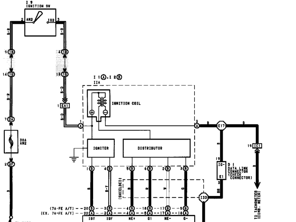
The first step to determine the kind of ignition coil is to know the terminology used. There are a variety of connections and terminals on an ignition wiring schematic which includes two primary as well as two secondary. Each coil has a specific operating voltage. To determine the type of coil you have the first step is to test the voltage at the S1 primary terminal. To determine if it is a Type A, C, or B coil, you should also test S1’s resistance.
The coil’s low-tension end must be connected with the chassis positively. This is exactly what you can find in the diagram of wiring. The high-tension side supplies positively direct to the spark plugs. To reduce the noise, the coil’s metal body must be connected to chassis. However, it is not necessary to electrically connect. There are also connections between the negative and positive coil’s terminals on an ignition wiring diagram. In certain instances it is possible to find the ignition coil is damaged and can be diagnosed with a scan at an auto parts store.
The black-and-white-striped wire from the harness goes to the negative terminal. The white wire is the other one. It is black with a trace on it, and it connects to the positive terminal. The black wire connects to the contactbreaker. You can remove the black wire from the plug housing by using a paperclip If you’re unsure of the connections. Also, make sure to ensure that the terminals haven’t been bent.
Accessory Terminals
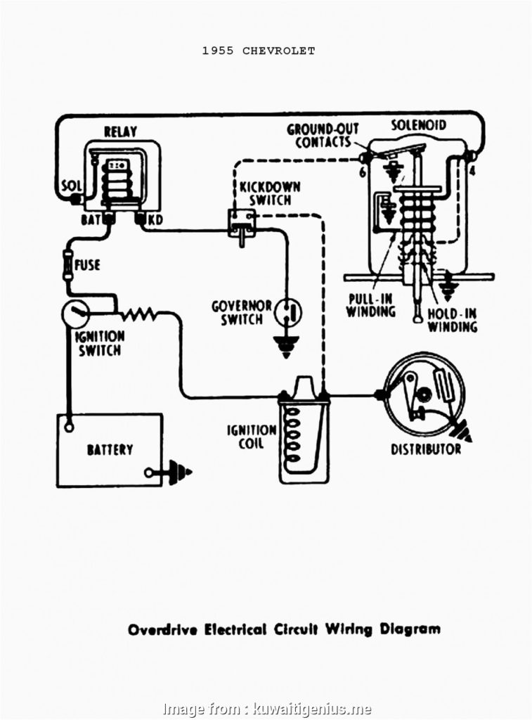
Diagrams of ignition wiring show the wiring used in the power supply of the vehicle. Each component is equipped with four distinct connections that are color coded. The red color is for accessories, yellow the battery, and green the starter solenoid. The “IGN terminal” is used to provide power to the wipers and other operating features. The diagram demonstrates how to connect the ACC and ST terminals to the rest of the components.
The terminal BAT connects the battery to the charger. Without the battery the electrical system can not begin. In addition, the switch will not start. The wiring diagram will tell you where to find the battery of your car. The ignition switch as well as the battery are connected by the accessory terminals. The BAT terminal is connected to the battery.
Some ignition switches come with the option of an “accessory position” which allows users to adjust their outputs independently of the ignition. Customers may want to utilize the auxiliary output independently of the ignition. The auxiliary output can be connected by wiring the connector in the same colors as the ignition, and then attaching it to the ACC terminal of the switch. Although this is a useful feature, there is one important difference. Most ignition switches are set to be in an ACC position when the vehicle is in the ACC position, while they’re set to the START position when the car is in the IGN position.
Gallery of Toyota Ignition Coil Wiring Diagram
Gallery of Toyota Ignition Coil Wiring Diagram


