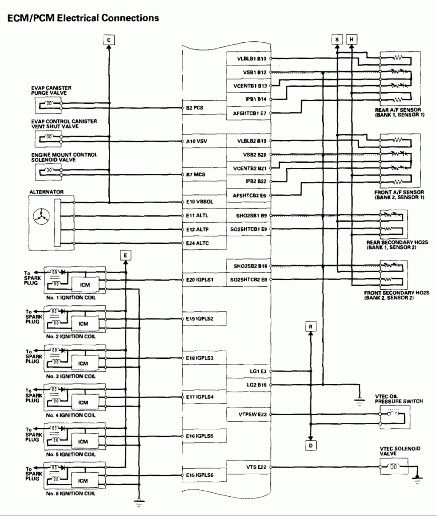
2004 Honda Accord Ignition Wiring Diagram – Let’s start by looking at different types terminals found on the ignition switch. These terminals comprise the Ignition switch as well as the Coil as well as the Accessory. Once we have established the purpose of these terminals are used for then we can discover the various components of the 2004 Honda Accord Ignition Wiring Diagram. We’ll also discuss the functions of both the Ignition Switch and Coil. Following that, we will move on to the Accessory Terminals.
Terminals for the ignition switch

An ignition switch has three different switches that direct the battery’s current to various destinations. The ON/OFF state of the switch that controls the ignition is managed by the third switch, which delivers power to the choke whenever it’s pushed. Different manufacturers have distinct color-coding systems that correspond to the conductors. OMC uses the same method. Connectors can be connected to the ignition switch to include a digital Tachometer.
Although the majority of ignition switch terminals aren’t original, the numbering for each may not match the diagram. The first step is to check the continuity of all wires to make sure they’re properly plugged into the ignition switches. A cheap multimeter can help you do this. Once you’ve verified that the wires are in good condition, you can install the connector. The wiring loom used for an ignition switch that’s supplied by the factory will be different from the one you have in your vehicle.
Before connecting the ACC outputs to the auxiliary outputs of your car, it is important to be familiar with the fundamentals of these connections. The ACC/IGN connections function as the default connections on the ignition switch. The START/IGN terminals connect to the radio or stereo. The ignition switch acts as the engine’s on/off button. On older vehicles the ignition switch’s terminals are identified with the alphabets “ACC”, and “ST” (for distinct magnetic wires).
Terminals for coil
To figure out the type of ignition coil, the first step is to learn the terminology. There are a variety of connections and terminals within an ignition wiring schematic, including two primary, and two secondary. The coils are equipped with a particular operating voltage. The initial step in determining which type you’ve got is to check the voltage on S1, the main terminal. S1 should also undergo resistance tests to determine if it are a Type A or B coil.
The coil with low tension must be connected at the chassis’ minus. This is the ground on the wiring diagram for ignition. The high tension side supplies positive directly the spark plugs. To prevent noise the body of the coil is required to be connected to the chassis. It is not necessary to connect the coil electrically. There are also connections between the positive and negative coil terminals on the ignition wiring diagram. You may find an issue with your ignition coil that can be easily diagnosed by looking it up at an auto parts store.
The black-and-white-striped wire from the harness goes to the negative terminal. The positive terminal is connected to the white wire, which has the trace of black. The black wire connects to the contactbreaker. It is possible to remove the black wire from the housing of the plug with a paper clip if you are unsure about the connections. Make sure that the terminals aren’t bent.
Accessory terminals
Ignition wiring diagrams show the different wires that are used to power the car’s various components. There are usually four color-coded terminus for each component. Red refers to accessories, yellow to the battery and green is the starter solenoid. The “IGN” terminal is used to turn on the car, operate the wipers, and other features. The diagram illustrates the connection to the ACCand ST terminals.
The terminal called BAT is the place where the battery is. The battery is vital for the electrical system to get started. Additionally, the switch doesn’t turn on. To find your car’s battery look over your wiring diagram. The ignition switch is linked to the car’s battery. The BAT terminal is connected with the battery.
Certain ignition switches come with an accessory setting where users can modify their outputs as well as control them without needing to use the ignition. Some customers want an auxiliary output that can be used independently from the ignition. To allow the auxiliary output to be used, plug in the connector to the same color as that of the ignition. Then connect it with the ACC end of the switch. This feature of convenience is fantastic, but there is one differentiator. Many ignition switches can be set to have an ACC position once the car is in the ACC position. They also will be in the START position after the vehicle has been entered the IGN position.
Gallery of 2004 Honda Accord Ignition Wiring Diagram

Gallery of 2004 Honda Accord Ignition Wiring Diagram


