Basic Ignition Switch Wiring Diagram – Let’s begin by examining the different types and purposes of the terminals that are found in the ignition switches. These are terminals for the Ignition, Coil, or Accessory. Once we know the purpose of each type of terminal, we can then determine the components of the ignition wiring. Then, we will discuss what functions are available for the Ignition switch and the Coil. After that we will discuss the Accessory Terminals.
Terminals for the ignition switch
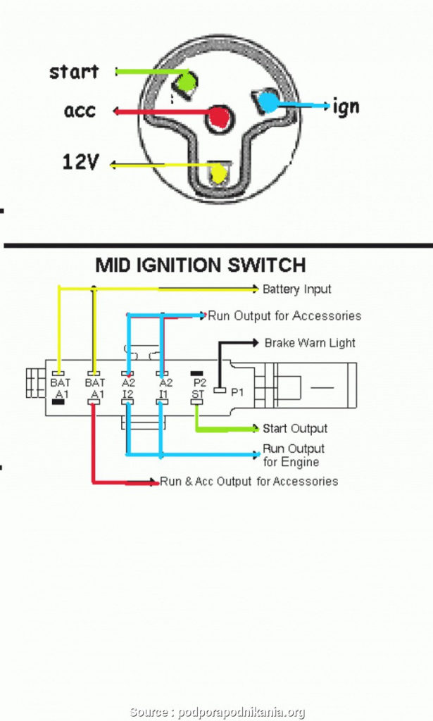
The ignition switch is comprised of three separate switches that feed the battery’s power to various destinations. The choke is powered by the first switch. The third switch regulates the ON/OFF of the ignition switch. Different manufacturers use different color-coding methods for different conductors. We’ll discuss this in another article. OMC follows this system. The connector allows for the attachment of a speedometer to the ignition switch.
While many ignition switch terminals could not be authentic, the numbering of each may not match the diagram. Before you plug in the ignition switch, be sure to test the continuity. A cheap multimeter can assist you in this. When you’re happy with the continuity it’s time to connect the new connector. The wiring loom of a factory-supplied ignition system switch differs.
To connect the ACC outputs to the auxiliary outputs of your vehicle, you have first know how these two connections work. The ACC, IGN and START terminals are the primary connections to the ignition switch. They also function as the primary connections to your radio and stereo. The ignition switch switches the car’s engine on and off. The terminals of older vehicles’ ignition switches are labeled by “ACC” as well as ST (for the individual magneto wires).
Terminals for coil
Understanding the terminology utilized is the first step in determining what kind of ignition coil you need. A basic ignition wiring diagram will reveal a variety of terminals and connections, comprising two primary and two secondaries. The voltage that operates on each coil differs. This is why it is crucial to test the voltage at S1 (primary terminal). S1 must also be inspected for resistance in order to identify if it’s a Type B, B or an A coil.
The lower-tension side of the coil should be connected to the chassis the negative. This is the base of the wiring for ignition. The high tension side supplies positively directly to the spark plugs. The body of the coil has to be connected to the chassis to prevent it from being smothered however it isn’t electrically necessary. The diagram for the ignition wiring will also reveal how to connect the negative and positive coil terminals. Sometimes, a damaged ignition coil can be detected with a scan in an auto parts shop.
The black-and-white-striped wire from the harness goes to the negative terminal. The other white wire has a black color and connects to the terminal opposite. The black wire connects to the contact breaker. It is possible to check the connections with a paperclip to pull the wires out from the housing. Make sure you verify that the connections haven’t been bent.
Accessory Terminals
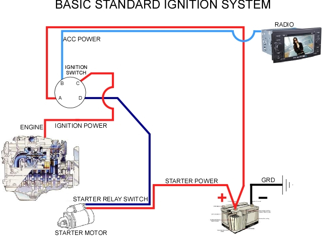
Ignition wiring diagrams show the different wires that are utilized to power the vehicle’s various components. There are usually four colors-coded terminus of each part. The red color is used for accessories, yellow is for the battery, while green is the starter solenoid. The “IGN terminal lets you start the car, manage the wipers, and any other functions. The diagram illustrates the connection to the ACCand ST terminals.
The terminal BAT holds the battery. The battery is vital for the electrical system to start. The switch will not turn on if the battery isn’t present. If you don’t know where your car’s battery is situated, look at your wiring diagram to see how to locate it. The ignition switch and battery are connected through the accessory terminals. The BAT terminal is connected to the battery.
Certain ignition switches come with an “accessory” position that allows users to control their outputs without having to use the ignition. Sometimes, customers would like the auxiliary output to be operated independently of the ignition. The auxiliary output can be used by wiring the connector with the same color as your ignition, and then attaching it to the ACC terminal of the switch. This option is useful, but it has one major distinction. The majority of ignition switches are configured to have an ACC status when the car is at the ACC or START position.
Gallery of Basic Ignition Switch Wiring Diagram
Gallery of Basic Ignition Switch Wiring Diagram


