Tractor Ignition Switch Wiring Diagram – In the beginning, we’ll look at the different types of terminals that are found on the ignition switch. These terminals include the Ignition switch, the Coil along with the Accessory. Once we have identified the terminals that are utilized then we can identify the different components of the Tractor Ignition Switch Wiring Diagram. We will also cover the functions of both the Ignition Switch and the Coil. Following that, we’ll shift our attention to Accessory terminals.
Terminals for ignition switches
An ignition switch has three separate switches that feed the battery’s current to different destinations. The ON/OFF state of the ignition switch is controlled by the first switch, which supplies the choke with power when it’s pushed. Different manufacturers have distinct colors-coding systems to match the conductors. OMC utilizes this system. The ignition switch comes with a connector for adding the Tachometer.
Although the majority of ignition switch terminals don’t have an initial number, they could be equipped with a different number. Before plugging into the ignition switch be sure to test the continuity. You can check this using a simple multimeter. After you’ve confirmed that the wires are in good condition, you can connect the connector. If you are using an ignition switch that is supplied by the manufacturer the wiring loom may be different from that used in your vehicle.
First, understand the differences between the ACC and the auxiliary outputs. The ACC and IGN connectors are the standard connections of your ignition switch. The START, IGN, and ACC terminals are primary connections for the radio or stereo, the START/IGN connections are the main ones. The ignition switch’s function is to turn the engine of your car on and off. Older cars are identified by the initials “ACC”, “ST”, (for individual magneto cables) at their ignition switch’s terminals.
Terminals for coil
The first step in determining the type of ignition coil is to know the terminology that is used. An understanding of the basic wiring diagram for ignition will show you a number of connections and terminals. The coils have a specific operating voltage. The initial step to determine which one you have will involve testing the voltage at S1, the primary terminal. S1 must also go through resistance testing to determine whether it’s an A or B coil.
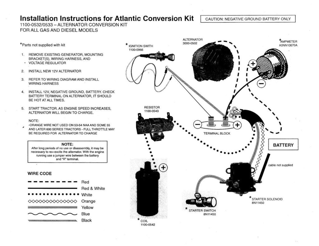
The coil’s low-tension side must be connected with the chassis positive. This is also the ground in the diagram of ignition wiring. The high-tension side is a positive connection to the sparkplugs. The metal body of the coil needs to be connected to the chassis to prevent it from being smothered however it isn’t electrically necessary. The wiring diagram for ignition will also indicate the connections of the positive coil’s terminals. In some cases, a scan at your local auto parts shop will be able to diagnose malfunctioning ignition coils.
The black-and-white-striped wire from the harness goes to the negative terminal. The negative terminal is served by the trace in black that’s joined to the white wire. The black wire connects to the contact breaker. To confirm the connection, employ a paperclip, or a pencil to lift them out of the housing for the plug. You should also check to see that the terminals aren’t bent.
Accessory terminals
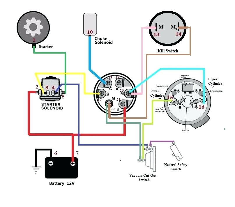
Diagrams of ignition wiring show the various wires that are used to power various components. Each part has four distinct connections that are color coded. The red color represents accessories, yellow represents the battery, and green for the solenoid for starters. The “IGN” terminal is used to turn on the car , and also to operate the wipers and other operating functions. The following diagram illustrates how to connect the ACC terminal and ST terminals to other components.
The terminal called BAT is the place where the battery is. The electrical system won’t start without the battery. A dead battery can cause the switch to stop turning on. It is possible to refer to your wiring diagram if you’re uncertain about where the car’s batteries are located. The accessory terminals of your car are connected to the ignition switch as well as the battery. The BAT Terminal is connected to the battery.
Some ignition switches come with a separate “accessory” location, which allows users can control their outputs without the ignition. In some cases, users may want to utilize the auxiliary output separately from the ignition. You can utilize the secondary input by connecting the connector to the ACC terminal. This is an excellent feature, however there’s one important distinction. A majority of ignition switches feature an ACC position when the car is in the ACC mode and a START position when you are in IGN.
Gallery of Tractor Ignition Switch Wiring Diagram
Gallery of Tractor Ignition Switch Wiring Diagram


