Wiring Diagram For Ignition Coil – Let’s first look at the different terminals used on the ignition switch. These terminals include the Ignition switch and Coil and the Accessory. Once we’ve determined the function of the terminals it is possible to recognize the various parts of the ignition wiring. We’ll also discuss the different functions of the Ignition Switch and Coil. Following that, we’ll shift our attention to Accessory terminals.
Terminals for ignition switch
Three switches can be found in an ignition switch. Each of these switches transmits the battery’s current to a variety of locations. The ON/OFF state of the ignition switch is controlled by the third switch, which delivers the choke with power when it is pushed. Every manufacturer has its individual color-coding system that we’ll discuss in a subsequent article. OMC utilizes this method. A connector is also included inside the ignition switch to allow attaching the Tachometer.
Although the majority of ignition switch terminals don’t carry an original number, they may have a different number. To ensure that your wires are properly plugged in to the switch, it is recommended to check their continuity. This can be done using an inexpensive multimeter. After you’re happy with the integrity of your wires, you will be able to connect the new connector. If your vehicle is equipped with an installed ignition switch the wiring diagram may differ.
To connect the ACC outputs to the auxiliary outputs on your vehicle, you have to understand the way these two connections function. The ACC and IGN terminals are the default connection on the ignition switch. the START and IGN terminals are the primary connections for the stereo and radio. The ignition switch is the one that turns the engine of your car on and off. Older cars are identified with the alphabets “ACC”, “ST”, (for individual magneto cables) at their ignition switch terminals.
Terminals for coil
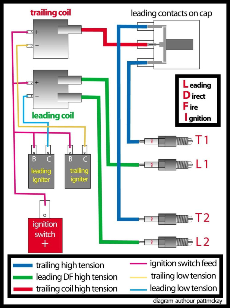
The first step in determining the kind of ignition coil is to understand the terms employed. A basic diagram of the wiring will reveal a variety of connections and terminals. It is essential to identify the kind of coil you have by testing the voltage on the primary terminal S1. To determine if it is a Type A, C, or B coil you must also test the resistance on S1’s.
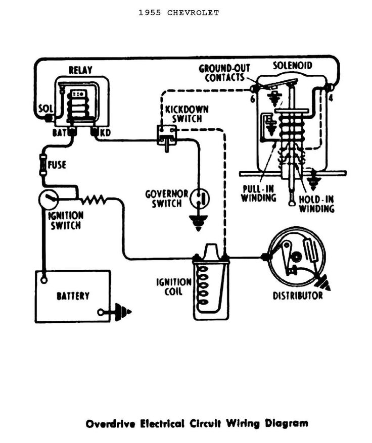
The chassis’ negative must be connected to the low-tension side. This is the wiring diagram you will see in the wiring diagram. The high-tension component supplies positively direct to the spark plugs. The aluminum body of the coil has to be connected to the chassis to prevent it from being smothered, but it isn’t electrically required. The wiring diagram will illustrate the connection between the positive and negative coils. In certain instances scanning your local auto parts shop will help identify malfunctioning ignition coils.
The black-and-white-striped wire from the harness goes to the negative terminal. The positive terminal receives the white wire with the black trace. The black wire connects to the contact breaker. You can check the connections with a paperclip to pull the wires out of the housing. Be sure to check that the terminals haven’t been bent.
Accessory Terminals
The ignition wiring diagrams illustrate the different wires that are used to power the car’s various parts. There are generally four color-coded terminals that correspond to each component. Red is used for accessories and yellow is for the battery, while green is for the solenoid for starters. The “IGN terminal lets you start your car, operate the wipers, or any other operation features. The diagram illustrates how to connect ACC or ST terminals, and other.
The terminal BAT is where the battery is. Without the battery, the electrical system does not begin. A dead battery can cause the switch to not turn on. The wiring diagram will show you where to find your car’s battery. The ignition switch and the battery are connected through the accessory terminals. The BAT terminal is connected with the battery.
Some ignition switches have the “accessory” setting that allows users to regulate their outputs without having to use the ignition. Customers sometimes want the auxiliary output to be operated independently of the ignition. It is possible to use the additional input by connecting it to the ACC terminal. This is a great feature, however there’s one important difference. The majority of ignition switches are set to have an ACC position when the vehicle is in the ACC position, whereas they’re in the START position when the vehicle is in the IGN position.
Gallery of Wiring Diagram For Ignition Coil
Gallery of Wiring Diagram For Ignition Coil


