Wiring Diagram For Points Ignition – We will first look at the various types and purposes of the terminals that are found in the ignition switches. These include terminals for Coil, Ignition Switch, and Accessory. Once we know what these terminals do and what they do, we can then be able to identify the various parts of the ignition wiring. We’ll also discuss the functions and the Coil. Following that, we’ll shift our attention to Accessory terminals.
Terminals for the ignition switch

The ignition switch is comprised of three different switches that direct the battery’s current to different destinations. The ON/OFF setting of the ignition switch is controlled by the first switch, which provides power to the choke when it’s pulled. Each manufacturer has their unique color-coding system, which we’ll discuss in a subsequent article. OMC uses this system. The ignition switch comes with an option to connect an timer.
While many ignition switch terminals don’t appear in their original configuration however, the numbers may not match the diagram. Check the continuity of all the wires to make sure they’re properly plugged into the ignition switches. A multimeter that is inexpensive can assist you in this. When you’re satisfied with the continuity of the wires, then you’ll be able to connect the new connector. The wiring loom used for an ignition switch that’s supplied by the manufacturer will differ from the one you have in your car.
In order to connect the ACC outputs to the auxiliary outputs on your car, you’ll need first know the way these two connections function. The ACC terminals and IGN terminals function as the default connections to the ignition switch. The START and IGN connections are the primary connections for stereo and radio. The ignition switch is the engine’s off/on button. Older vehicles have ignition switch terminals marked “ACC” or “ST” (for individual magnetowires).
Terminals for coil
Understanding the terms used is the initial step in determining the type of ignition coil. The fundamental diagram of ignition wiring shows a number different connections and terminals. There are two primary and one secondary. It is essential to identify the type of coil you have by testing the voltage on the primary terminal S1. To determine if it is a Type A, C or B coil, it is recommended to also test S1’s resistance.
The coil’s low-tension end is to be connected to the chassis’ positive. This is what’s called the ground in the wiring diagram for ignition. The high-tension supply supplies positive directly to spark plugs. For suppression purposes the coil’s metal body is required to be connected to the chassis. It’s not necessary for electrical use. The wiring diagram for the ignition will demonstrate how to connect the terminals of the positive and negative coils. In certain instances it is recommended to conduct a scan at the local auto parts store will help identify the malfunctioning ignition coils.
The black-and-white-striped wire from the harness goes to the negative terminal. The white wire also is black with a trace, and it connects to the positive terminal. The black wire connects to the contactbreaker. If you’re not certain about the connections of the twowires, use a paper clip to remove them from the plug housing. It’s also crucial to ensure that the terminals aren’t bent.
Accessory terminals
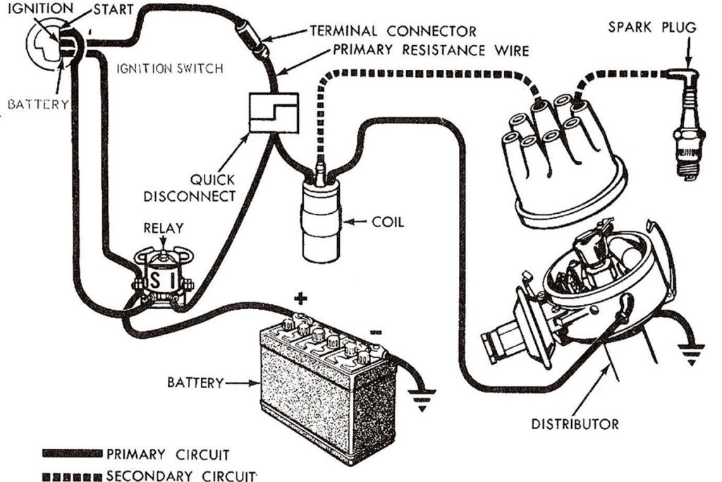
Diagrams of ignition wiring illustrate the wires used in the vehicle’s power supply. There are generally four color-coded terminals to each component. The red symbol represents accessories, yellow represents the battery and green for the solenoid for starters. The “IGN” terminal is used to start the car, operate the wipers, and other features. The diagram below shows how to connect the ACC terminal as well as the ST terminals to the other components.
The battery is connected to the terminal called BAT. The electrical system cannot begin without the battery. In addition the switch isn’t turned on. If you’re not sure of where your car’s battery is situated, you can look at your wiring diagram to see the best way to find it. The ignition switch and the battery are connected by the accessory terminals. The BAT connector connects to your battery.
Some ignition switches have the “accessory” position that permits users to control their outputs , without needing to utilize the ignition. Some customers prefer to use an auxiliary output that is not connected to the ignition. Use the additional output by connecting the connector to an ACC terminal on the switch with the same colors. While this is an excellent feature, there’s something you need to know. Most ignition switches come with the ACC position when your vehicle is in the ACC mode, and a START position when the switch is in IGN.
Gallery of Wiring Diagram For Points Ignition

Gallery of Wiring Diagram For Points Ignition


