67 Mustang Ignition Switch Wiring Diagram – We will first examine the various types of terminals in the ignition switch. These terminals include the Ignition switch, the Coil as well as the Accessory. When we have a clear understanding of the purpose of each terminal, we can then determine the components of the ignition wiring. We’ll also discuss the functions of both the Ignition Switch and Coil. After that we will discuss the Accessory Terminals.
Terminals for ignition switches
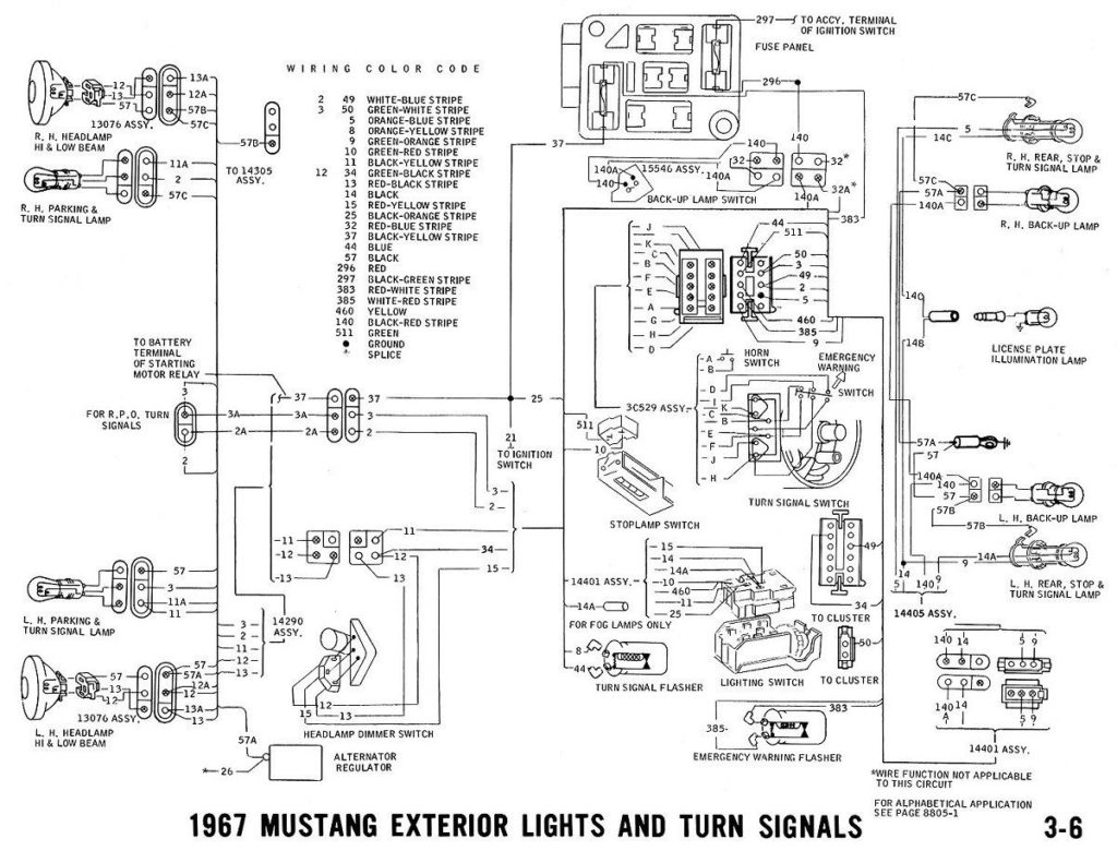
Three switches are located on the ignition switch. Each of the three switches is able to feed the battery’s voltage to several different places. The ON/OFF setting of the switch that controls the ignition is managed by the second switch, which provides the choke with power when it’s pushed. Different manufacturers use their own color-coding systems for the various conductors, which is documented in another article. OMC uses this method. Connectors can be connected to the ignition switch to include a digital Tachometer.
Even though most ignition switch terminals do not have an original number, they might have a different one. Verify the continuity of the wires first to make sure they’re properly connected to the ignition switch. This can be checked with a simple multimeter. Once you’re satisfied about the integrity of the wires, then you’ll be able to connect the new connector. If your car is equipped with an original factory-supplied ignition switch (or a wiring loom) The wiring loom may differ from the one in your car.
It is important to know the differences between the ACC and secondary outputs. The ACC and IGN connectors are the default connections for your ignition switch. Although the START, IGN, and ACC terminals are primary connections for the radio or stereo, the START/IGN terminals are the primary ones. The ignition switch turns the engine of your car ON and OFF. The terminals of older cars ignition switches are identified with “ACC” as well as ST (for specific magneto wires).
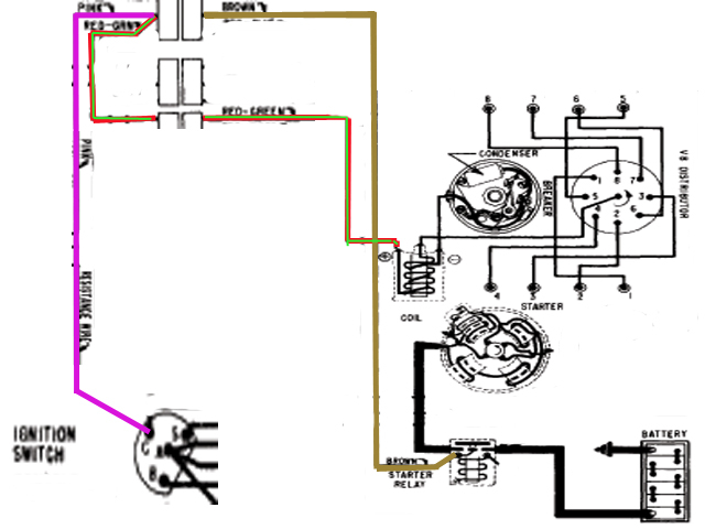
Terminals for Coil
Understanding the terms that is used is the initial step to finding out the right kind of ignition coil to choose. An understanding of the basic wiring diagram for ignition will provide you with a range of connections and terminals. You must determine the type of coil you own by examining the voltage on the primary terminal, S1. S1 must be checked for resistance to determine if the coil belongs to Type A, B, and/or C.
The coil’s low-tension side must be connected to the chassis positively. This is the ground on the wiring diagram for ignition. The high-tension end supplies positive direct to the sparkplugs. To reduce the noise, the coil’s metal body must be connected to the chassis. But, it’s not necessary to connect the coil electrically. The wiring diagram for the ignition will show you how to connect the two terminals of the positive or negative coils. In certain instances, a scan at your local auto parts shop will help identify the malfunctioning ignition coils.
The black-and-white-striped wire from the harness goes to the negative terminal. The white wire also has a black trace on it and it connects to the positive terminal. The black wire connects to the contactbreaker. You can remove the black wire from the housing of the plug using a paper clip in case you are uncertain about the connection. It is also important to see that the terminals aren’t bent.
Accessory terminals
Diagrams of ignition wiring depict the wiring used to supply power to different parts of the car. Each component is equipped with four distinct colored connections. Red is for accessories while yellow is the battery, while green is the solenoid for starters. The “IGN” terminal can be utilized to turn on the car, control the wipers and other functions. The diagram demonstrates how to connect the ACC and ST terminals to the other components.
The terminal BAT is where the battery is. The battery is vital to allow the electrical system to begin. A dead battery can cause the switch to stop turning on. If you’re not sure the exact location where the battery in your car is situated, you can review your wiring diagram to figure out how to locate it. The accessory terminals of your car are connected to the battery and the ignition switch. The BAT connector is connected to the battery.
Some ignition switches come with the option of an “accessory position” that lets users modify their outputs independent of the ignition. Sometimes, users want to make use of an additional output that is not connected to the ignition. The auxiliary output is connected to connect the connector with the same colors as your ignition, and then connecting it to the ACC terminal of the switch. This feature is convenient however it does have one key difference. Most ignition switches will have an ACC position when the vehicle is in the ACC however, they will be in the START position if the car is in IGN.
Gallery of 67 Mustang Ignition Switch Wiring Diagram
Gallery of 67 Mustang Ignition Switch Wiring Diagram


