Car Ignition System Wiring Diagram – Let’s start by looking at different types of terminals in an ignition switch. These are terminals for the Ignition, Coil, or Accessory. Once we’ve determined the function of these terminals, it is possible to recognize the various parts of the ignition wiring. In addition, we will discuss the function of the Ignition switch and Coil. After that, we will focus on the accessories terminals.
The terminals are for ignition switches.
There are three different switches in the ignition switch, and they feed the battery’s voltage to several different places. The ON/OFF setting of the switch that controls the ignition is managed by the second switch, which delivers power to the choke when it is pushed. Different manufacturers have different color-coding systems that correspond to the conductors. OMC utilizes the same system. The connector permits the attachment of a speedometer to the ignition switch.
While the majority of ignition switch terminals don’t have an original number, they may have a different one. Check the continuity of all the wires to ensure they are correctly connected to the ignition switches. This can be done using an inexpensive multimeter. Once you’ve verified the continuity of the wires you are able to install the connector. If you have a factory-supplied ignition switch the wiring loom may be different from that used in your vehicle.
You must first understand the way that ACC outputs and auxiliary outputs work in order to join them. The ACC and IGN terminals are the default connections for your ignition switch, and the START and IGN terminals are the main connections for the stereo and radio. The ignition switch switches the car’s engine ON and OFF. The terminals of the ignition switch on older cars are identified with the letters “ACC” and “ST” (for individual magneto wires).
Terminals for Coil
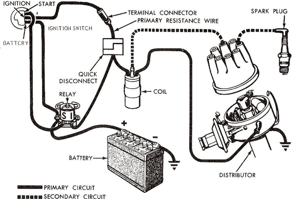
The terms used to define the model and type of an ignition coil is the primary thing. An ignition wiring diagram will display a range of terminals and connections, including two primary and two secondary. It is essential to identify the type of coil you have by testing the voltage on the primary terminal, called S1. To determine whether it’s an A, C or B coil, you must also check the resistance of S1.
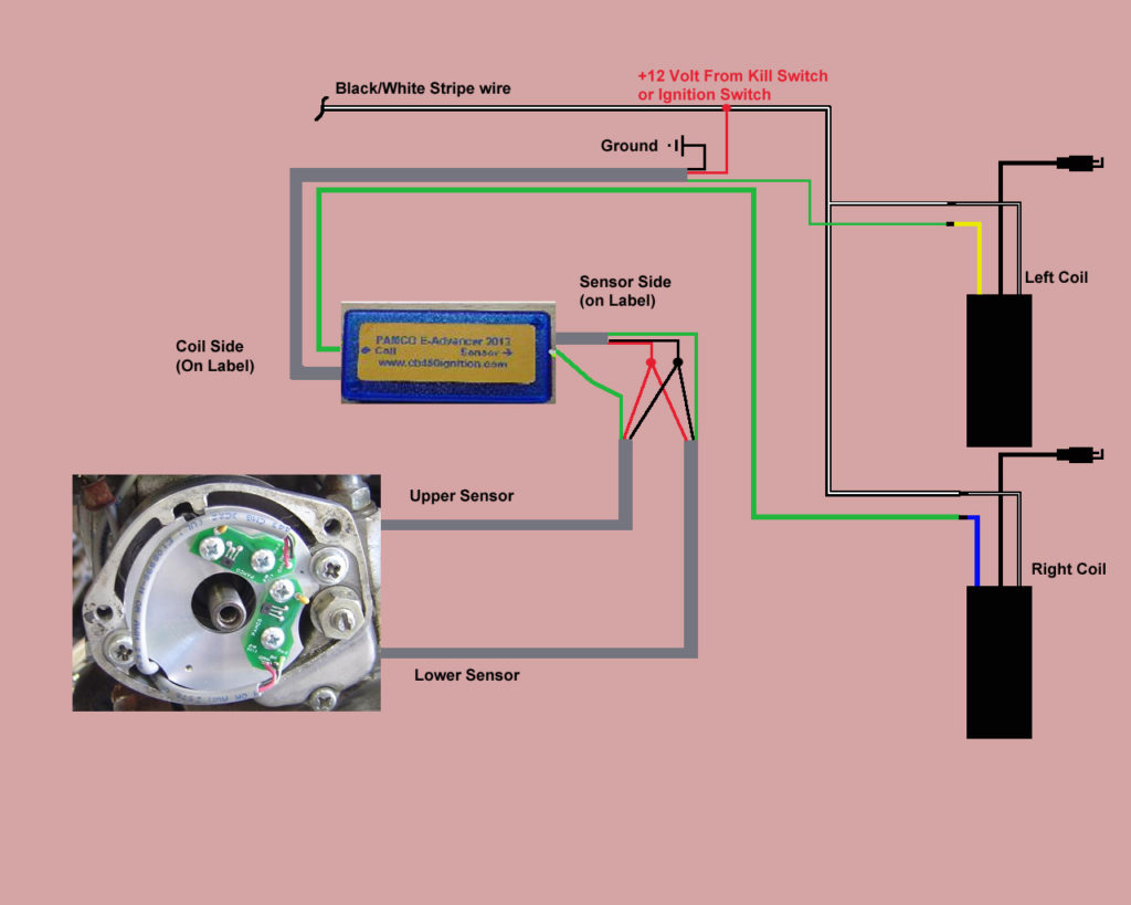
The low-tension end of the coil needs to be connected to the chassis the negative. This is what’s called the ground on the wiring diagram for ignition. The high-tension component connects the spark plugs to a positive. To prevent noise the body of the coil must be connected to the chassis. It is not necessary to connect the coil electrically. The diagram of the ignition wiring will also demonstrate the connection of the positive and negative coil terminals. In certain instances, a scan at your local auto parts store will help identify the malfunctioning ignition coils.
The black-and-white-striped wire from the harness goes to the negative terminal. The terminal for the negative is served by the black trace connected to the white wire. The black wire connects to the contact breaker. If you’re not certain about the connections between the two, try using a paper clip to remove them from the plug housing. Be sure the terminals aren’t bent.
Accessory terminals
The diagrams for ignition wiring depict the wiring used in the vehicle’s power supply. There are usually four different colored terminals for each component. Red is for accessories while yellow is the battery, and green is the starter solenoid. The “IGN terminal” is used to provide power to the wipers and other operating features. The diagram shows the connections to the ACC- and ST terminals.
The terminal BAT is the connection to the battery. The electrical system is not able to start without the battery. Also, the switch won’t turn on without the battery. The wiring diagram will tell the location of the battery of your car. The ignition switch and the battery are connected via accessory terminals. The BAT connector is connected to the battery.
Certain ignition switches have an accessory setting where users can alter their outputs and control them without the need to use the ignition. Sometimes, customers want to utilize an auxiliary output that is separate from the ignition. In order for the auxiliary output be used, connect the connector in the same shade as that of the ignition. Connect it to the ACC end of the switch. While this is an excellent feature, there’s something you need to know. The majority of ignition switches have an ACC position if the car is in ACC however, they will be at the START position if the car is in IGN.
Gallery of Car Ignition System Wiring Diagram
Gallery of Car Ignition System Wiring Diagram


