Ford 8n Electronic Ignition Wiring Diagram – First, we will look at the various types of terminals on the ignition switch. These include the terminals for the Ignition switch, Coil, and Accessory. Once we understand the function of each kind of terminal, we can then identify the various components of the ignition wiring. We’ll also discuss the functions of the Ignition switch, as well as the Coil. Then, we’ll focus to the accessory terminals.
Terminals for the ignition switch
An ignition switch has three switches. They feed the battery’s voltage to many different locations. The first switch powers the choke. The third switch regulates the ON/OFF switch of the ignition switch. Different manufacturers use their own color-coding systems for different conductors that is described in a separate article. OMC follows this scheme. An adapter is included on the ignition switch to allow the installation of the tonometer.
Even though the majority of ignition switch terminals don’t have the original design, the numbering may not match that of the diagram. Check the continuity of the wires first to make sure they’re properly connected to the ignition switch. A multimeter is a great tool to check the continuity. After you’re happy with the continuity of your wires, you will be able to install the new connector. The wiring loom of an ignition system switch that is supplied by the manufacturer is distinct.
Knowing how the ACC outputs are connected to the other outputs inside your vehicle is crucial. The ACC and IGN connectors are the default connections for your ignition switch. While the START, IGN, and ACC terminals are the primary connections for radios or stereo, the START/IGN connections are the primary ones. The ignition switch acts as the engine’s off/on button. On older cars the terminals of the ignition switch are identified with the alphabets “ACC” as well as “ST” (for distinct magnetic wires).
Terminals for coil
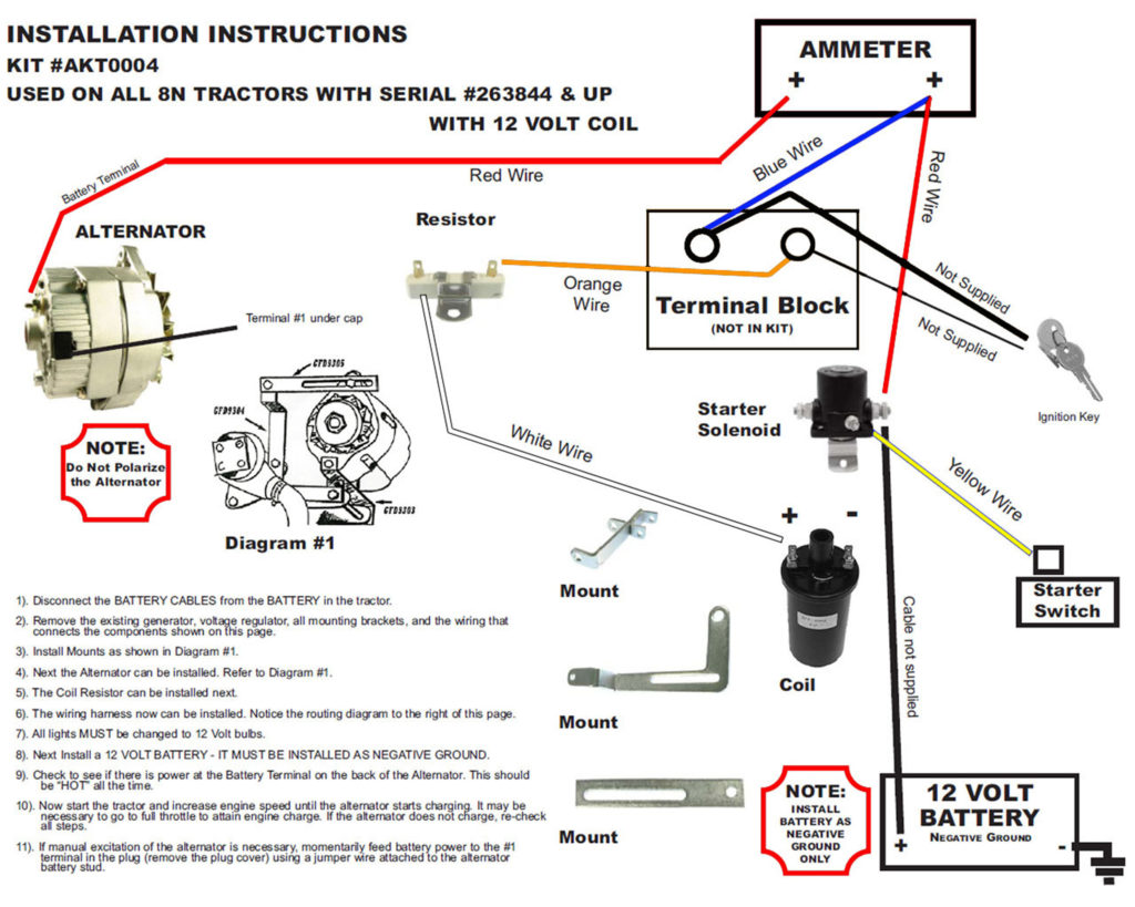
The first step to determine the kind of ignition coil is to know the terminology employed. You will see several connections and terminals on a basic ignition wiring schematic which includes two primary as well as two secondary. The voltage that operates on each coil differs. It is important to first test the voltage at the S1 (primary terminal). To determine whether it’s a Type A, C, or B coil, you must also test the resistance on S1’s.
The coil’s low-tension end is to be connected to the chassis’ positive. This is the wiring diagram you will see on the diagram of wiring. The high-tension supply provides the spark plugs with positive electricity directly. It is required to suppress the body of the coil’s metal be connected to the chassis, however it isn’t essential. The wiring diagram for ignition will also indicate the connection of the positive coil’s terminals. In certain cases scanning your local auto parts store can help you identify the malfunctioning ignition coils.
The black-and-white-striped wire from the harness goes to the negative terminal. The positive terminal also receives the white wire that has a black trace. The contact breaker is linked to the black wire. To test the connections between the two wires employ a paperclip to lift them from the housing. Make sure that the connectors aren’t bent.
Accessory Terminals
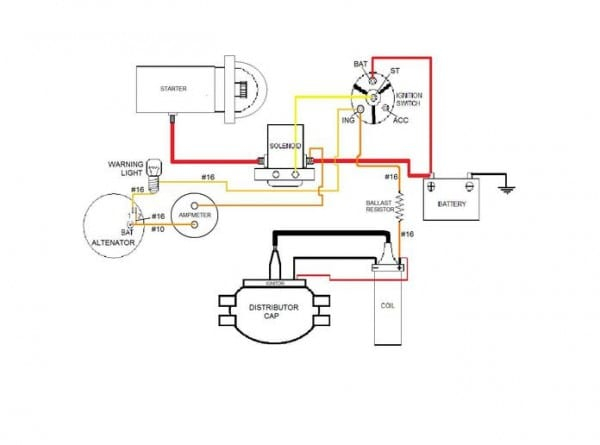
The diagrams for ignition wiring show the wires used to power the vehicle’s electrical supply. There are generally four color-coded terminals that correspond to the respective component. Red refers to accessories, yellow the battery and green is the starter solenoid. The “IGN” terminal is used to start the car, operate the wipers and other functions. The diagram demonstrates how to connect the ACC and ST terminals to the rest of the components.
The battery is attached to the terminal called BAT. The battery is vital for the electrical system to get started. The switch will not turn on if there is no battery present. You can refer to your wiring diagram if you are unsure where your car’s batteries are located. The accessory terminals in your vehicle are connected to the battery and ignition button. The BAT terminal is connected to the battery.
Some ignition switches come with the option of an “accessory position” that lets users modify their outputs independent of the ignition. In some cases, users may want to use the auxiliary output separately from the ignition. To make use of the additional output, wire the connector in the same colors as ignition, connecting it to the ACC terminal on the switch. This feature of convenience is fantastic however there’s a distinction. Most ignition switches come with an ACC position when the car is in the ACC mode and a START mode when it is in IGN.
Gallery of Ford 8n Electronic Ignition Wiring Diagram
Gallery of Ford 8n Electronic Ignition Wiring Diagram


