Ford Ranger Ignition Wiring Diagram – We will first look at the different types of terminals on the ignition switch. These are terminals for the Ignition, Coil, or Accessory. Once we’ve established the purpose of the terminals we can identify the various parts of the ignition wiring. We’ll also discuss the roles of the Ignition switch, as well as the Coil. Following that, we’ll shift our attention to the Accessory terminals.
Terminals for ignition switches
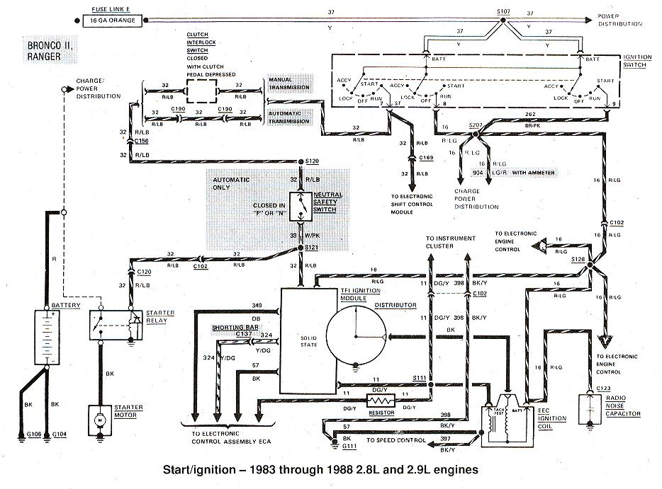
There are three separate switches in the ignition switch, and they transmit the battery’s current voltage to a variety of locations. The first switch is utilized to power the choke through pushing it. Then, another switch controls the ON/OFF position. Different manufacturers have distinct colors-coding systems to match the conductors. OMC utilizes this system. The ignition switch is also equipped with an adapter for the addition of the tachometer.
While most ignition switch terminals can be duplicated, the numbers might not match the diagram. Examine the electrical continuity first to ensure that they’re properly connected to the ignition switch. A multimeter is an excellent instrument to verify the continuity. After you’re sure that all wires are in good order, you can attach the new connector. If you have an ignition switch supplied by the manufacturer, the wiring loom is different from that used in your vehicle.
Understanding how the ACC outputs are connected to the other outputs inside your vehicle is crucial. The ACC and IGN terminals are the default connections on your ignition switch. the START and IGN terminals are the main connections for stereo and radio. The ignition switch is the one that turns the engine of your car on and off. Older vehicles have ignition switch terminals labeled “ACC” or “ST” (for individual magnetowires).
Terminals for coil
Understanding the terminology used is the initial step in determining the kind of ignition coil you need. The basic ignition wiring diagram illustrates a variety of connections and terminals. There are two primary and one secondary. Each coil is equipped with a distinct operating voltage. To determine which type of coil you’ve got first, you need to determine the voltage at the S1 primary terminal. S1 must be tested for resistance in order to identify if the coil is Type A, B, or C.
The low-tension side of the coil needs to be connected to the chassis”negative. This is exactly what you can find in the wiring diagram. The high tension side supplies positive directly the spark plugs. To prevent noise, the coil’s metal body must be connected to chassis. However, it is not necessary to electrically connect. The diagram of the ignition wiring will also reveal how to connect the positive and negative coil’s terminals. Sometimes, a damaged ignition coil is identified with a scan at an auto repair shop.
The black-and-white-striped wire from the harness goes to the negative terminal. The negative terminal is served by the trace in black that’s attached to the white wire. The black wire connects to the contact breaker. To check the connections between the two wires, use a paperclip to lift them out of the housing. Be sure to verify that the connections aren’t bent.
Accessory Terminals
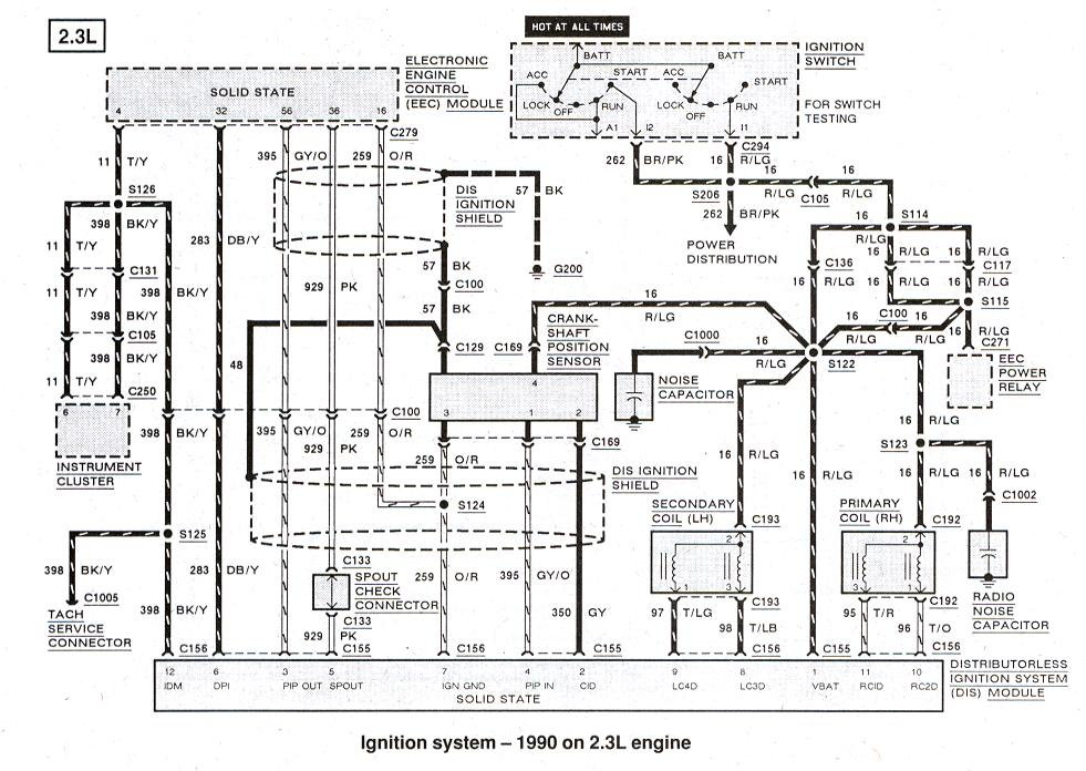
The diagrams for ignition wiring show the wiring used in the vehicle’s power supply. There are generally four colors-coded terminus of each part. The red symbol represents accessories, yellow represents the battery, and green for the starter solenoid. The “IGN” terminal can be utilized to turn on the car, control the wipers, as well as other features. The diagram shows how to connect ACC or ST terminals as well as the rest.
The battery is attached to the terminal whose name is BAT. The battery is essential for the electrical system to get started. The switch also won’t turn on without the battery. You can refer to your wiring diagram if uncertain about where the car’s batteries are. Your car’s accessory terminals are connected to the ignition switch and the battery. The BAT terminal is connected to the battery.
Some ignition switches feature an “accessory” position that allows users to control their outputs , without having to use the ignition. Some customers may prefer to use the auxiliary output independently of the ignition. The auxiliary output is used to connect the connector in the same colors as the ignition, and then connecting it to the ACC terminal of the switch. Although this is a useful feature, there is one important difference. The majority of ignition switches are set to be in an ACC position when the vehicle is in the ACC position, but they’re in the START position when the car is in the IGN position.
Gallery of Ford Ranger Ignition Wiring Diagram
Gallery of Ford Ranger Ignition Wiring Diagram


