Honda Motorcycle Ignition Coil Wiring Diagram – We will first look at the various types and functions of the terminals in the ignition switches. These terminals comprise the Ignition switch, the Coil along with the Accessory. After we’ve identified the terminals that are utilized, we can begin to recognize the various parts of the Honda Motorcycle Ignition Coil Wiring Diagram. We will also talk about the functions and the Coil. We will then concentrate on the accessory terminals.
Terminals of ignition switch
An ignition switch has three switches. They feed the battery’s voltage to many different locations. The first switch is the one that supplies the choke with power, and the third switch toggles the state of the switch. Different manufacturers have different color codes for various conductors. This is described in another article. OMC uses the same method. The connector permits the attachment of a speedometer to the ignition switch.
While many ignition switch terminals could not be original, the numbers of each may not match the diagram. Check the integrity of the wires to determine if they’re connected to the ignition switch correctly. A multimeter that is inexpensive can assist you in this. Once you are satisfied with the integrity of the wires, connect the new connector. If your vehicle is equipped with an ignition switch that is installed, the wiring diagram will differ.
It is important to understand the ways in which the ACC outputs and the auxiliary outputs function in order to join them. The ACC/IGN connections function as the default connections for the ignition switch. The START/IGN connections connect to the radio or stereo. The ignition switch acts as the engine’s off/on button. Older cars have the ignition switch terminals marked “ACC” or “ST” (for individual magnetowires).
Terminals for coil
The first step to determine the type of ignition coil is to know the terminology that is used. The diagram of the basic ignition wiring depicts various connections and terminals. There are two primary and one secondary. You need to determine the type of coil you have by testing the voltage on the primary terminal, called S1. S1 should be examined for resistance to identify if the coil belongs to Type A, B, and/or C.
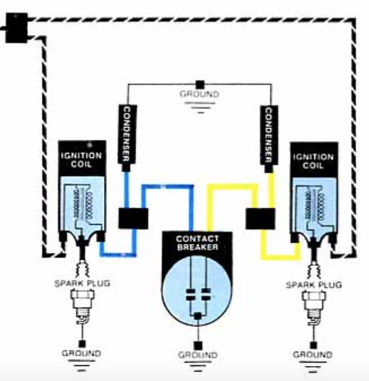
The chassis’ negative must be connected to the side of low-tension. It is also the ground in an ignition wiring diagram. The high-tension part provides positive direct to the sparkplugs. The coil’s metal body needs to be connected to the chassis to suppress the effect, but it is not electrically necessary. A wiring diagram can also show the connection between the positive and negative coil terminals. Sometimes, a visit to an auto parts store could identify a problem with the ignition wire.
The black-and-white-striped wire from the harness goes to the negative terminal. Positive terminal gets the second white wire, which includes a black trace. The black wire is connected to the contact breaker. To verify the connection, use a paperclip or a pencil to remove them of the plug housing. It is also important to ensure that the terminals don’t bend.
Accessory terminals
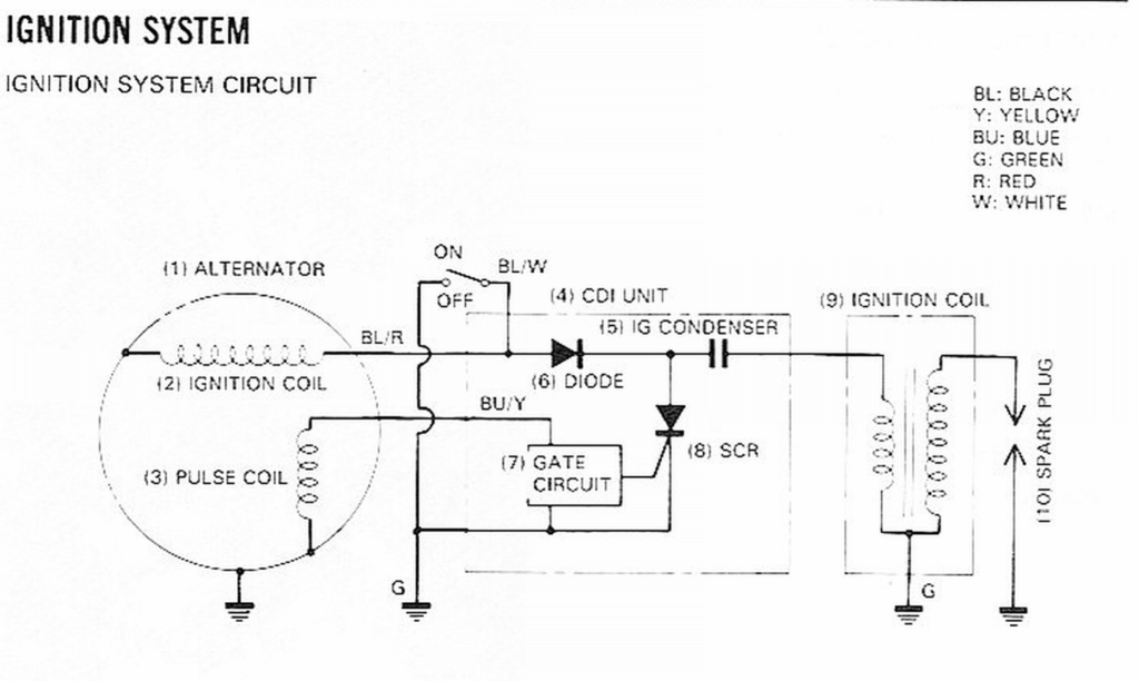
The wiring diagrams for the ignition show the different wires that provide power to the various parts of the vehicle. There are generally four colored terminus lines for each component. The red symbol represents accessories, yellow represents the battery and green for the solenoid for starters. The “IGN terminal” is used to provide power to the wipers as well as other operating features. The diagram illustrates how you can connect ACC or ST terminals, and other.
The terminal BAT holds the battery. The electrical system will not start when the battery isn’t connected. In addition, the switch doesn’t turn on. If you don’t know the location of your car’s battery located, you can examine your wiring diagram to figure out the best way to find it. The accessory terminals in your car are connected to the battery as well as the ignition switch. The BAT Terminal is connected to the Battery.
Certain ignition switches come with an “accessory” setting that permits users to regulate their outputs without needing to turn on the ignition. Users may wish to utilize the auxiliary output independently of the ignition. To make use of the auxiliary output, wire the connector using the same colors as ignition, connecting it to the ACC terminal on the switch. This convenience feature is great however, there’s one difference. A lot of ignition switches can be set to have an ACC location when the car has been moved into the ACC position. They’ll also be in the START mode after the vehicle has been entered the IGN position.
Gallery of Honda Motorcycle Ignition Coil Wiring Diagram
Gallery of Honda Motorcycle Ignition Coil Wiring Diagram


